Low Battery Problems in Energy Storage Systems: Common Causes and Solutions
author: HT Infinite Power
2026-11-03
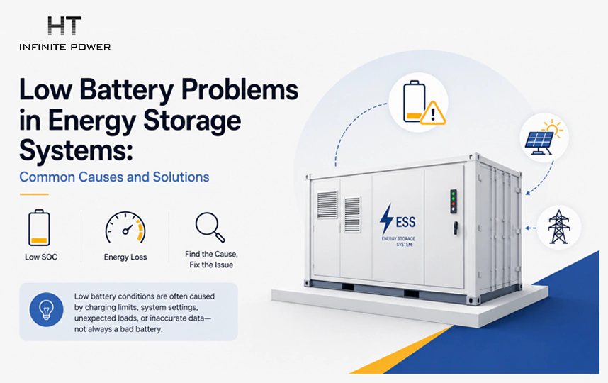
A battery energy storage system (BESS) that remains at a low state of charge (SOC), fails to charge fully, or loses stored energy faster than expected does not necessarily have a defective battery. In commercial and industrial installations, low battery conditions can result from insufficient charging power, restricted operation, control settings, unexpected facility loads, battery protection limits, or inaccurate monitoring data.
The challenge is identifying which part of the system is responsible. A battery may be ready to accept energy but receive insufficient power from the photovoltaic (PV) system or grid. Alternatively, the power conversion system (PCS) may limit charging, the battery management system (BMS) may restrict operation, or the energy management system (EMS) may be following a schedule that prioritizes another operating objective.
These problems can produce similar symptoms while requiring very different solutions.
This guide examines common low battery problems in commercial and industrial energy storage systems, explains how to distinguish their underlying causes, and outlines practical troubleshooting methods. The focus is on the complete BESS operating system rather than battery cells in isolation.
1. Understand What a Low Battery Condition Actually Means
Before investigating why an energy storage system is not charging or appears to be draining quickly, it is important to distinguish between battery state of charge, available capacity, and power.
State of charge (SOC) indicates how much charge or energy remains in the battery relative to its defined full-charge reference. A low SOC means the battery currently has a relatively small amount of stored energy available within its operating limits. It does not automatically mean the battery has lost capacity or developed a fault.
For example, a battery displaying 20% SOC may simply have discharged during normal operation and need to recharge. If the same battery repeatedly stops charging at a low level despite adequate charging opportunities, further investigation is necessary.
Three measurements are particularly important:
- SOC (%): The battery's estimated remaining charge relative to its reference capacity.
- Power (kW): The instantaneous rate at which the battery charges or discharges.
- Energy (kWh): The amount of energy stored or transferred over time.
These measurements describe different conditions. A system may have sufficient remaining energy but be unable to deliver the required power. Conversely, it may have a high charging-power capability but receive too little energy over the available charging period to reach its target SOC.
It is also necessary to distinguish low SOC from reduced battery capacity. A battery that has degraded may store less energy when fully charged than it could when new. However, its SOC display could still reach 100%. Capacity degradation therefore cannot be diagnosed from a low SOC reading alone.
The first step is to establish whether the problem concerns insufficient energy input, restricted charging, excessive discharge, reduced battery capacity, or incorrect SOC reporting.
2. Insufficient Energy Input: The Battery Cannot Charge Without Available Power
One of the most straightforward causes of low battery SOC is insufficient energy input. The battery may be operating normally, but the available charging source cannot provide enough energy to meet the required charging schedule.
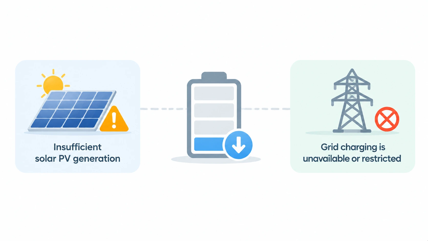
Insufficient solar PV generation
In solar-plus-storage installations, battery charging often depends on surplus PV generation after the facility's electricity demand has been served.
Consider a commercial building with a rooftop PV system. During periods of strong solar generation, the PV system may produce more electricity than the building consumes, allowing the surplus to charge the battery. On cloudy days, however, PV output may fall below the facility's demand. Little or no surplus energy remains for charging.
A similar situation occurs when PV production is concentrated in a short midday period but the battery needs more charging energy than that period can supply.
The important distinction is between total PV generation and energy actually available for battery charging. A PV system producing substantial daily energy does not guarantee that the battery will receive enough energy. Facility consumption, export restrictions, inverter limits, and charging priorities all affect the available surplus.
How to identify the cause:
Compare PV generation, facility consumption, grid import and export, and battery charging power over the same time intervals. If the battery is not charging because the facility is consuming nearly all available PV output, the limitation is the energy balance rather than necessarily a battery fault.
Possible solutions:
- Review whether the PV system has sufficient generation during the intended charging period.
- Check whether the facility's load profile leaves enough surplus energy for charging.
- Review export restrictions and PV inverter operating limits.
- Consider grid charging if the project configuration, electricity tariff, and operating strategy allow it.
- Reassess the charging schedule against seasonal PV production rather than relying only on expected sunny-day output.
Grid charging is unavailable or restricted
Some commercial BESS installations use grid electricity to recharge when PV generation is insufficient. However, grid charging may be restricted by the EMS, utility interconnection requirements, tariff strategy, or site operating rules.
For example, an EMS may permit charging only during off-peak tariff periods. If the battery has discharged significantly during the day but the scheduled charging window has not yet started, its SOC may remain low even though the grid connection is available.
Other installations may have limits on grid import or charging power. A battery designed to charge at a particular rate cannot necessarily draw that power if the site's electrical infrastructure or operating settings impose a lower limit.
How to identify the cause:
Check whether grid charging is enabled, whether the charging schedule is active, and whether the site meter records the expected grid import. Compare the configured charging limit with the actual power delivered to the PCS.
Possible solutions:
Review the EMS schedule, tariff settings, grid import limits, and charging permissions. Where grid charging is permitted, adjust the operating schedule to provide sufficient charging time without exceeding site or utility constraints.
3. Charging Power Is Limited by the PCS or System Configuration
A battery may have sufficient energy available from the PV system or grid but still charge more slowly than expected. In this situation, the issue may be the maximum charging power permitted by the PCS or another system-level constraint.
The PCS converts electrical power between the AC system and the battery's DC side. During charging, it converts AC power into DC power and regulates the charging process according to system commands and operating limits.
The actual charging power is determined by the most restrictive relevant limit, which may include:
- The PCS's maximum charging power.
- The battery's permitted charging current and voltage.
- The BMS charging limit.
- Available PV or grid power.
- Site import restrictions.
- EMS charging commands and operating schedules.
For example, a battery system may have a PCS rated for 100 kW, but the BMS may currently permit only 40 kW of charging because of battery temperature or cell operating conditions. The PCS cannot simply override that restriction. Similarly, if the EMS commands 30 kW of charging, the battery will not necessarily use the full 100 kW capability.
This explains why a system can appear to have adequate equipment capacity but still charge slowly under actual operating conditions.
How to identify the cause:
Compare the PCS rated power, configured charging-power limit, actual charging command, BMS permitted charging current, and measured charging power. Check whether the system is consistently operating below its expected limit or whether the restriction appears only under particular conditions.
Possible solutions:
- Verify the PCS charging-power configuration against the project design.
- Check whether the BMS is actively limiting charging.
- Review grid import and PV power constraints.
- Confirm that EMS commands match the intended charging strategy.
- Check whether the battery and PCS ratings are appropriately matched.
Do not increase charging limits simply to force faster charging. The battery manufacturer's permitted operating conditions and the system's protection settings must remain in effect.
4. BMS Protection and Battery Temperature Restrict Charging
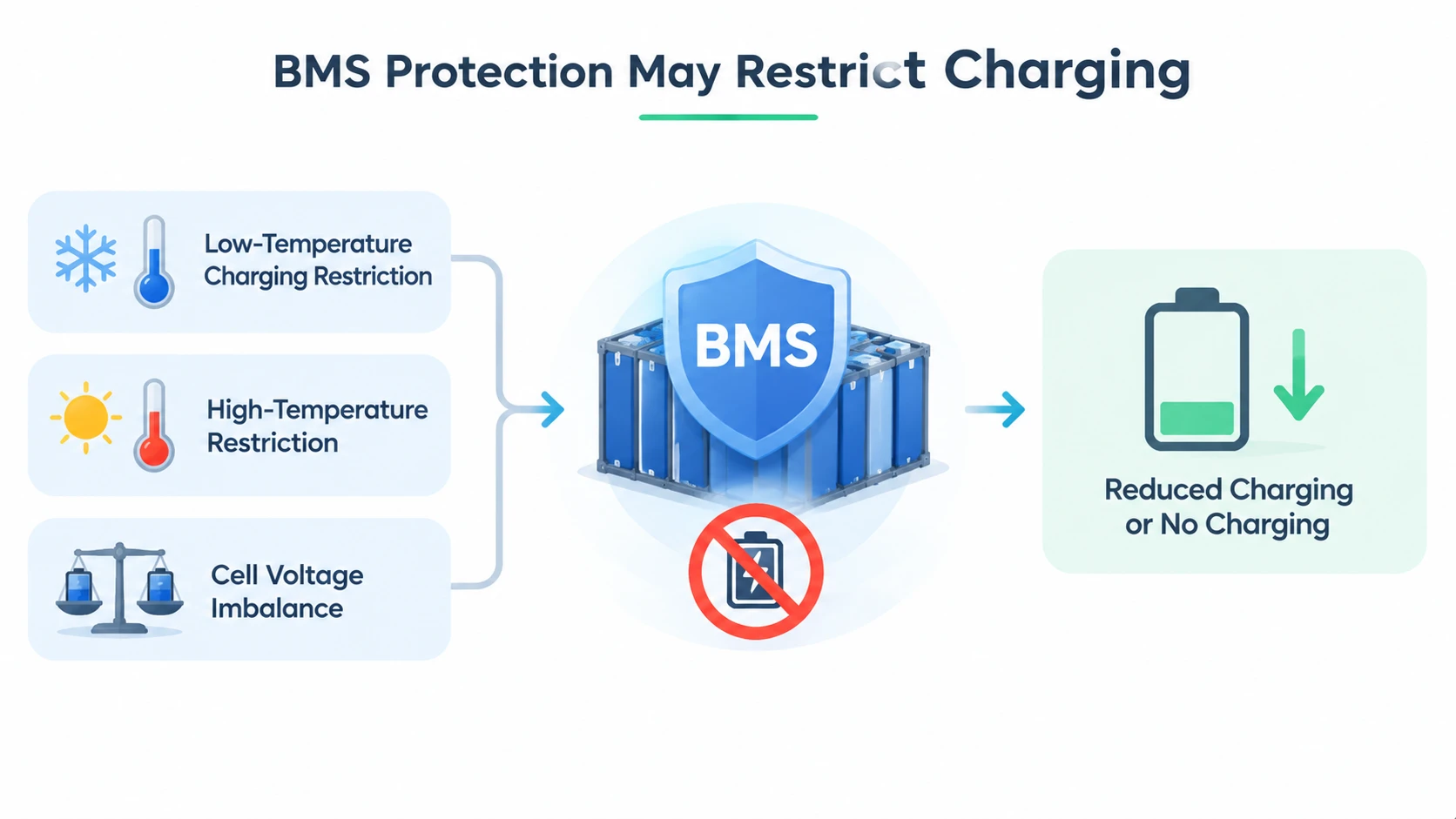
The BMS monitors battery operating conditions and protects cells from operating outside their permitted limits. It typically monitors cell voltage, current, and temperature, and may also manage cell balancing and communicate operating restrictions to the PCS or EMS.
When the BMS detects an abnormal or unsuitable condition, it may reduce the permitted charging current, prevent charging, or isolate part of the battery system.
These actions can leave the battery at a low SOC even when a charging source is available.
Low-temperature charging restrictions
Battery charging capability depends on cell chemistry and temperature. For lithium-ion batteries, charging at temperatures below the manufacturer's permitted range can create conditions that damage cells, including lithium plating under certain circumstances.
To prevent this, the BMS may restrict charging current or block charging until the battery reaches an acceptable temperature.
This can occur in outdoor BESS installations during cold weather, particularly when the system has been idle for an extended period. The battery may appear healthy, but it cannot accept the expected charging power until its temperature returns to the permitted operating range.
How to identify the cause:
Review cell temperature readings, ambient temperature, BMS alarms, and the permitted charging current. If charging restrictions coincide with low cell temperatures, temperature management is a likely factor.
Possible solutions:
Check the battery heating or thermal-management system and verify that it operates according to the manufacturer's requirements. Allow the battery to reach its permitted charging temperature before expecting normal charging performance.
High-temperature restrictions
Excessive battery temperature can also restrict charging. High temperatures may result from elevated ambient conditions, inadequate cooling, blocked airflow, cooling-system faults, or demanding operating conditions.
The BMS may reduce charging power to prevent further temperature increases. If the temperature continues to exceed the permitted range, charging may be stopped.
In this case, the low SOC is a consequence of a protective response. Increasing the charging command will not resolve the underlying problem.
How to identify the cause:
Check temperature measurements across battery modules or racks rather than relying only on the enclosure's ambient temperature. Review cooling-system alarms, coolant temperatures or flow where applicable, fan operation, and differences between battery sections.
Possible solutions:
Inspect the cooling system, airflow paths, filters, fans, pumps, and temperature sensors according to the manufacturer's maintenance procedures. Investigate uneven temperature distribution, since a localized hot area may restrict the operation of a larger battery section.
Cell voltage imbalance
Battery cells connected in series do not always maintain identical voltage and SOC. Small differences can develop during operation and may become more significant as the battery ages or experiences uneven operating conditions.
During charging, the highest-voltage cell may reach its permitted upper voltage limit before the remaining cells are fully charged. The BMS may then reduce charging current or stop charging to protect that cell.
This can make the overall battery appear unable to reach its expected SOC, even though some cells still have room to accept additional charge.
How to identify the cause:
Examine individual cell or module voltage data, voltage differences across the battery, balancing status, and relevant BMS warnings. A consistently abnormal voltage difference is more informative than the overall SOC reading alone.
Possible solutions:
Allow the BMS to perform its designed balancing process where appropriate. If the imbalance persists, have qualified personnel investigate the affected modules, connections, and battery-management functions. Do not bypass voltage protection or force additional charging to make the displayed SOC increase.
The UK government's guidance on grid-scale energy storage emphasizes continuous monitoring of battery voltage, temperature, current, communication status, and BMS alarms as part of safe system operation.
5. EMS Settings and Charging Schedules Prevent the Battery from Reaching Its Target SOC
Not every low battery condition is caused by a hardware problem. In many commercial BESS installations, the EMS determines when the battery charges and discharges according to the project's operating strategy.
A battery may remain at a low SOC because the EMS is following its configured priorities rather than because it cannot charge.
For example, a facility using peak shaving may discharge its battery during periods of high demand. If the EMS schedules charging only during a later off-peak period, the battery may remain at a low level for several hours.
Other configurations may prioritize PV self-consumption, grid import limits, export control, backup reserves, or demand response. These priorities influence how much energy is directed into or out of the battery.
Several settings deserve particular attention:
- Charging schedule: Defines when charging is permitted.
- Target SOC: Determines the desired charging level under a particular operating mode.
- Minimum SOC: Establishes an operating boundary below which normal discharge may be restricted.
- Grid charging permission: Determines whether the system can charge from the grid.
- Power limits: Restrict charging or discharging according to the project configuration.
- Operating priority: Determines how the EMS balances different objectives.
A particularly important issue is the difference between a configured target and an actual charging command. An EMS may be set to reach 90% SOC, for example, but that target does not guarantee the battery will charge if the charging window is closed or the BMS is restricting current.
How to identify the cause:
Review the EMS operating mode, active schedule, target SOC, charging permissions, and command history. Compare these settings with the actual battery power and SOC trend.
Possible solutions:
Correct schedule conflicts, verify the intended operating priorities, and ensure that the configured target SOC is compatible with the battery's permitted operating range. After changing settings, verify the resulting charging behavior through measured power and SOC data.
6. Unexpected Discharging and Excessive Energy Consumption
A battery may charge normally but still remain at a low SOC because it discharges more frequently or consumes more energy than expected.
This problem is particularly relevant to commercial facilities with changing production schedules, seasonal loads, or multiple electrical systems connected to the same distribution network.
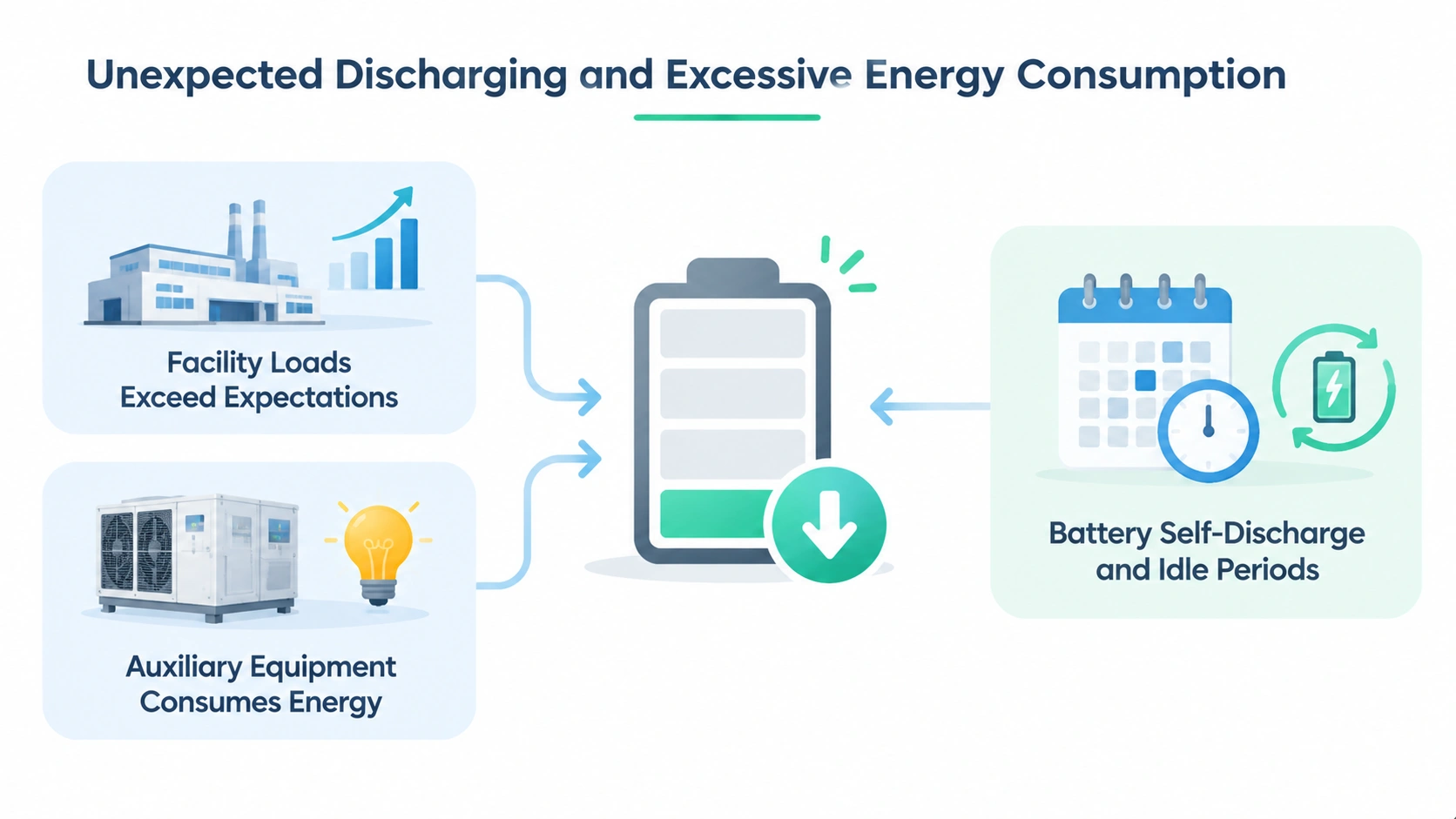
Facility loads exceed the expected demand
If facility consumption increases, the EMS may use more stored energy to support the load or reduce grid demand. A factory operating additional machinery, for example, may consume battery energy faster than expected during a peak-shaving period.
If the charging schedule does not adapt to the increased consumption, the battery may not recover its SOC before the next discharge period.
How to identify the cause:
Compare historical facility demand with current interval data. Check whether battery discharge power increases during the same periods as the unexpected load increase.
Possible solutions:
Update the EMS strategy using actual load profiles. Where appropriate, adjust the discharge schedule, reduce unnecessary loads, or provide additional charging time. If the original battery sizing was based on outdated consumption data, reassess whether the system still meets the facility's operating requirements.
Auxiliary equipment consumes energy
A BESS uses energy beyond the electricity delivered by its battery cells. Cooling equipment, control systems, communications, pumps, fans, and other auxiliary components may consume electricity during operation and standby.
For a large commercial system, these loads can become significant, particularly when the battery remains idle for extended periods or when thermal-management equipment operates continuously.
If the system's monitoring boundary includes auxiliary consumption, the displayed net energy balance may therefore differ from the battery's internal energy change.
How to identify the cause:
Review auxiliary power consumption, cooling-system operating hours, standby consumption, and the system's AC and DC energy measurements. Determine whether the apparent energy loss occurs inside the battery or through equipment connected to the BESS.
Possible solutions:
Investigate abnormal auxiliary consumption, inspect cooling equipment, and verify standby operating settings. Do not disable essential cooling, monitoring, or protection equipment merely to reduce energy consumption.
Battery self-discharge and idle periods
Batteries can gradually lose stored energy even when they are not actively supplying an external load. This is known as self-discharge. The rate depends on battery chemistry, temperature, storage conditions, and the battery manufacturer's specifications.
In addition, an installed BESS may consume energy through its control and auxiliary systems while waiting for grid interconnection approval, commissioning, or operational authorization.
A system that remains idle for an extended period may therefore show a lower SOC than expected when it is finally prepared for operation.
How to identify the cause:
Compare the SOC trend during periods without scheduled charging or discharging. Check auxiliary consumption, historical operating records, and the duration of the idle period.
Possible solutions:
Follow the manufacturer's storage and maintenance requirements, including periodic SOC inspections and any prescribed conditioning procedures. Where a system has remained idle for a long time, have qualified personnel assess its condition before returning it to normal operation.
7. Battery Degradation Reduces Available Energy Over Time
Battery degradation is another possible contributor to recurring low battery conditions, but it should not be confused with ordinary low SOC.
As a battery ages, its ability to store and deliver energy can decline. This is commonly described as a reduction in state of health (SOH) or usable capacity. The battery may still charge to its reported full SOC, but the actual energy stored at that point may be lower than when the system was new.
For example, a battery originally capable of storing 500 kWh of usable energy may deliver less energy after years of operation because of capacity degradation. Its SOC display could still reach 100%, even though the amount of energy represented by that percentage has changed.
Degradation can be influenced by:
- Operating temperature and thermal conditions.
- Charging and discharging rates.
- Depth and frequency of cycling.
- Time spent at high or low SOC.
- Cell quality and manufacturing consistency.
- Battery operating history and maintenance.
The exact effects depend on the battery chemistry, cell design, and operating conditions. A low SOC reading alone is not sufficient evidence of degradation.
How to identify degradation
Compare current measured energy capacity with the original commissioning or acceptance-test results, using comparable operating conditions and measurement boundaries. Review SOH estimates, cumulative energy throughput, cycle history, and the battery manufacturer's capacity-retention information.
A particularly useful indication is a repeated difference between expected and measured discharge energy. If the battery reaches its normal upper SOC limit but supplies noticeably less energy than it previously did under comparable conditions, reduced capacity may be involved.
Possible solutions
First, determine whether the observed change is consistent with normal aging or indicates abnormal degradation. Review operating temperature, charging and discharging patterns, and historical battery data.
If the measured performance falls outside the manufacturer's guaranteed limits, contact the supplier for a formal assessment. Depending on the battery design and warranty terms, corrective action may involve module replacement, battery augmentation, or other manufacturer-approved measures.
Do not assume that increasing the charging target or changing the SOC calibration will restore lost battery capacity.
8. Communication and SOC Monitoring Problems Create Misleading Readings
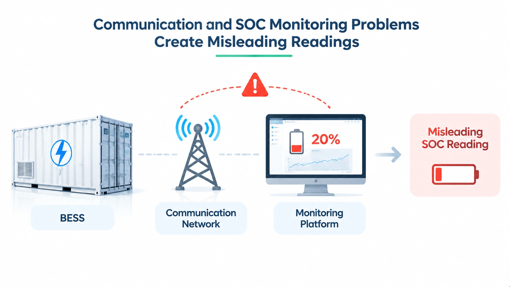
Sometimes the battery is operating normally, but the monitoring platform displays an incorrect or outdated SOC value. This can make a system appear to have a low battery problem when the actual issue lies in data acquisition or communication.
A commercial BESS may contain several layers of monitoring and control:
A commercial BESS may contain several layers of monitoring and control:
- The BMS monitors battery cells, modules, and racks.
- The PCS reports electrical operating conditions and power conversion status.
- The EMS coordinates charging and discharging commands.
- The site monitoring platform collects and displays system information.
These components exchange data through communication interfaces. If communication is interrupted, delayed, or incorrectly configured, the information displayed at the operator interface may not represent the current battery condition.
Communication interruptions
A communication failure between the BMS and EMS can prevent the EMS from receiving updated battery information or charging permissions. Depending on the system design, the PCS may reduce power, stop charging, or enter a protective operating state when required data is unavailable.
A communication issue can also affect individual battery racks. If the EMS cannot confirm the operating status of a rack, it may exclude that rack from normal operation.
How to identify the cause:
Check communication alarms, timestamps, data-update intervals, rack availability, and communication status between the BMS, PCS, and EMS. Compare the local battery controller's readings with the central monitoring platform.
Possible solutions:
Inspect communication connections, network devices, protocol settings, and controller status. Confirm that the correct devices are online and that data is being transmitted consistently. Any configuration changes should follow the system supplier's approved procedures.
Incorrect SOC estimation
SOC is an estimated operating parameter, not a direct measurement of stored energy in the same way that a meter measures electrical energy flow. Battery-management systems use information such as current, voltage, temperature, and battery models to estimate SOC.
Estimation errors can develop when the underlying measurements or model assumptions become inaccurate. For example, incorrect battery capacity parameters, current-sensor errors, or inconsistent battery operating data may cause the displayed SOC to drift away from the actual condition.
Some systems also perform SOC recalibration or correction under specific operating conditions. A sudden change in the displayed SOC may therefore reflect an estimation correction rather than an immediate physical loss of energy.
How to identify the cause:
Compare SOC values from the BMS and independent monitoring interfaces where available. Review current and voltage measurements, historical SOC changes, and any calibration or estimation alarms. Look for abrupt SOC jumps that cannot be explained by the measured charging or discharging energy.
Possible solutions:
Have qualified personnel verify measurement sensors, battery parameters, and SOC estimation settings against the manufacturer's requirements. Do not manually adjust SOC values simply to make the display match an expected figure.
The importance of reliable BMS monitoring and communication is also reflected in IEEE 2686-2024, which addresses BMS configuration, protection, and interoperability in stationary energy storage applications.
9. A Practical Troubleshooting Process for Low Battery Problems
When an energy storage system repeatedly remains at a low SOC or does not charge as expected, troubleshooting should follow the electrical and control sequence rather than immediately assuming battery failure.
A structured investigation helps identify where energy is being restricted or consumed.
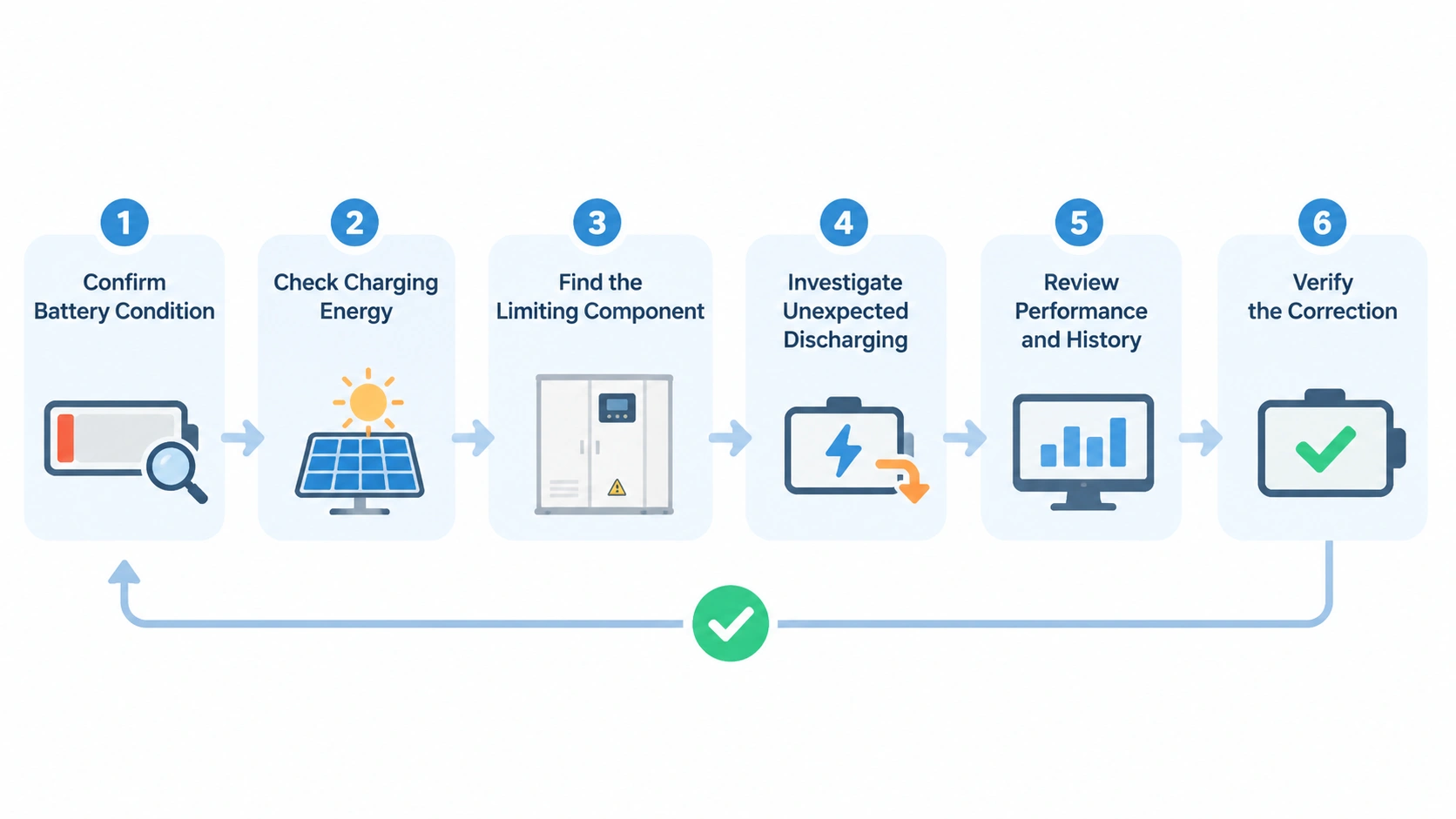
Step 1: Confirm the actual battery condition
Start by checking the SOC reported by the BMS and comparing it with the central monitoring platform. Review battery voltage, current, temperature, SOH, and relevant alarms.
Determine whether the battery is genuinely low or whether the displayed SOC may be inaccurate.
Step 2: Check whether charging energy is available
Review the PV generation and grid supply at the same time intervals as the battery's charging activity.
For a solar-plus-storage system, determine whether PV generation exceeds facility consumption and whether surplus energy is available. For grid charging, confirm that the grid connection and charging permissions are available.
If no charging energy is available, investigating the battery itself is unlikely to resolve the problem.
Step 3: Identify which component is restricting charging
Compare the following values:
- Actual charging power.
- PCS charging-power limit.
- EMS charging command.
- BMS permitted charging current.
- Battery temperature and voltage limits.
This comparison helps establish whether the restriction originates from the available power source, the PCS, the EMS, or the BMS.
Step 4: Investigate unexpected discharging
If charging is operating normally but SOC continues to fall, examine the facility load, battery discharge schedule, auxiliary consumption, and standby operating conditions.
Check whether the EMS is intentionally discharging the battery or whether unexpected loads are consuming stored energy.
Check whether the EMS is intentionally discharging the battery or whether unexpected loads are consuming stored energy.
Step 5: Review battery performance and system history
If the previous checks do not explain the problem, investigate cell imbalance, capacity degradation, sensor accuracy, and communication reliability.
Compare current operating data with historical records and commissioning measurements. Repeated trends are generally more useful than a single SOC reading.
Compare current operating data with historical records and commissioning measurements. Repeated trends are generally more useful than a single SOC reading.
Step 6: Verify the correction
After the underlying issue has been addressed, monitor the system through a complete operating cycle where practical. Confirm that charging power, SOC changes, discharge behavior, and alarms are consistent with the intended operating strategy.
For complex BESS faults, inspection and corrective work should be performed by qualified personnel following the manufacturer's procedures. Sandia's energy storage commissioning guidance highlights the importance of verifying BMS operation, communication across the control hierarchy, inverter controls, and whole-system operating functions.
10. How to Prevent Recurring Low Battery Problems
Troubleshooting addresses an existing problem, but preventing repeated low SOC conditions requires consistent monitoring and coordination across the complete energy storage system.
Several practices can improve operating reliability.
Monitor charging and discharging trends, not just SOC. Track battery SOC alongside charging power, discharging power, PV generation, grid import, and facility demand. This makes it easier to identify whether the battery is receiving insufficient energy or consuming more than expected.
Review EMS settings when operating conditions change. Changes in production schedules, electricity tariffs, PV output, or backup requirements may make the original charging and discharging strategy unsuitable. Periodically verify that the operating schedule still matches the facility's actual needs.
Maintain the battery thermal-management system. Check cooling or heating equipment, temperature sensors, airflow paths, pumps, and associated alarms according to the manufacturer's maintenance schedule. Temperature-related restrictions can otherwise become recurring causes of reduced charging performance.
Monitor cell-level operating data. Overall SOC can conceal differences between battery modules or racks. Reviewing cell voltage, temperature, balancing status, and BMS warnings helps identify developing problems before they significantly affect system availability.
Maintain communication and monitoring reliability. Confirm that the BMS, PCS, EMS, and site monitoring platform exchange accurate and timely information. Communication interruptions can affect both system control and fault diagnosis.
Keep operating and maintenance records. Record charging performance, discharge energy, alarms, corrective actions, and changes to operating parameters. Historical data makes it easier to distinguish a temporary operating restriction from a recurring equipment problem or gradual performance decline.
A preventive maintenance plan should follow the battery and system manufacturers' requirements. It should also define who is responsible for monitoring, fault response, software configuration, and periodic performance verification. UK government guidance for grid-scale energy storage similarly emphasizes continuous equipment monitoring, maintenance planning, fault records, and operation within specified limits.
Conclusion
Low battery problems in energy storage systems can originate from several parts of the installation. Insufficient PV or grid energy, charging-power restrictions, battery temperature, cell imbalance, EMS schedules, unexpected facility loads, degradation, and communication faults can all contribute to low SOC or slow charging.
The most effective approach is to investigate the complete energy and control chain. Confirm whether charging energy is available, identify whether the PCS or BMS is restricting power, examine EMS operating commands, and compare actual battery behavior with historical performance.
Most importantly, distinguish between normal operating restrictions and abnormal system conditions. A BMS limiting charging because of temperature or cell voltage is performing a protective function, not necessarily indicating equipment failure. Correct diagnosis should identify the reason for that restriction rather than bypassing it.
For commercial and industrial BESS installations, reliable operation depends on coordinated control of the battery, PCS, EMS, PV system, grid connection, and facility loads. Monitoring these components together provides a much clearer basis for resolving low battery conditions and maintaining consistent system performance.
Frequently Asked Questions
Why is my energy storage system not charging even when solar panels are generating electricity?
PV generation does not necessarily mean surplus energy is available for battery charging. The facility may be consuming most of the electricity, or the EMS may prioritize another operating mode. Charging may also be restricted by the PCS, BMS, battery temperature, or system configuration. Compare PV generation, facility demand, and actual battery charging power to identify the limitation.
Why does my battery charge more slowly than expected?
Charging speed depends on the available power source, PCS rating, BMS charging limits, battery temperature, and EMS commands. A system rated for high charging power may operate at a lower rate when the battery is cold, hot, near an operating limit, or subject to a configured charging restriction.
Why does my BESS battery lose charge overnight?
Possible causes include normal self-discharge, auxiliary electricity consumption, scheduled discharge, standby loads, and changes in SOC estimation. Check whether the battery is actually discharging into an external load or whether the observed reduction is associated with auxiliary consumption or monitoring behavior.
Does a low SOC mean the battery is damaged?
No. Low SOC indicates that the battery currently has relatively little stored energy within its operating range. It may simply need to recharge. Battery damage or degradation requires additional evidence, such as abnormal cell voltage, persistent imbalance, capacity loss, or relevant BMS alarms.
Why does my battery stop charging before reaching 100% SOC?
Possible reasons include a configured charging target, an upper operating limit, cell voltage imbalance, temperature restrictions, or BMS protection. The displayed SOC may also be affected by estimation or calibration. Check the EMS target, BMS status, and individual cell data before concluding that the battery has a fault.
Amps to Volts Calculator: Understanding Voltage Requirements in Battery Systems
Related Article