High-Voltage Direct-Connected PCS in Battery Energy Storage Systems
2026-03-13

Battery energy storage systems have traditionally followed a familiar architecture: the inverter operates at low voltage, and a step-up transformer raises the output to the medium-voltage grid. This structure has worked reliably for years and remains common in many installations.
However, an alternative approach is becoming increasingly visible in large-scale projects. Instead of using a transformer, the power conversion system can synthesize medium-voltage AC directly and connect to the grid bus. This architecture is usually referred to as a high-voltage direct-connected PCS.
At first glance, the change appears simple — remove the transformer and improve efficiency. In practice, the implications reach much further. Direct connection affects converter topology, insulation design, protection coordination, and even the long-term operational economics of the storage plant.
Understanding these changes is important for engineers and project developers evaluating modern battery storage architectures.
Why the transformer is being removed
Efficiency math in practice
The headline argument is simple: remove a conversion stage and you lose less energy. Run the numbers and it stops feeling like a marketing blip.
Take a typical conventional chain:
-
low-voltage PCS efficiency ≈ 98% (0.98)
-
step-up transformer efficiency ≈ 98.5% (0.985)
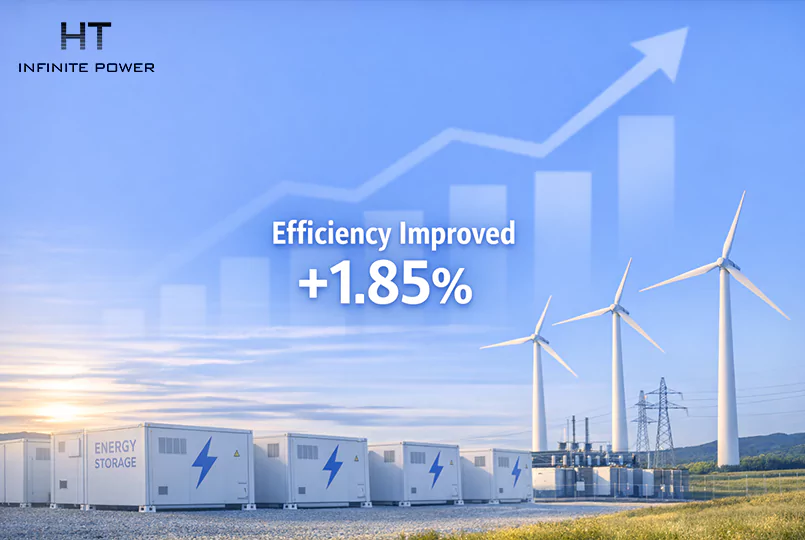
End-to-end efficiency = 0.98 × 0.985 = 0.9653, meaning roughly 96.5% of the battery energy reaches the medium-voltage side.
A directly synthesized high-voltage inverter at 98.5% efficiency yields an improvement of about 1.85 percentage points. That looks small until you multiply it by the plant’s annual throughput. For a plant dispatching 100,000 MWh/year, a 1.85% gain equals 1,850 MWh/year — not trivial. Monetize that in a jurisdiction with modest energy value and ancillary revenues, and the efficiency delta becomes an economic lever, not an academic footnote.
Milliseconds matter — services that pay for speed
The other reason is dynamic performance. Transformers have magnetics; they don’t like being asked to change on a millisecond timescale. Multilevel inverters control via semiconductor switching and digital loops that run in micro/millisecond domains. That speed enables participation in services that explicitly reward rapid response: fast frequency response, synthetic inertia, millisecond reactive compensation. Those are revenue streams that a transformer-buffered chain is less able to earn.
Building medium voltage from modular converters
Module count and voltage arithmetic
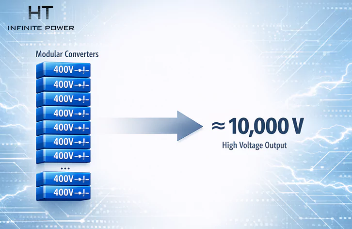
Conceptually the approach is straightforward: stack lots of manageable modules instead of building one giant high-voltage stage. The arithmetic is literal and useful for procurement planning.
If a module’s DC link is about 400 V, you need about 25 modules in series to synthesize ~10 kV:
If a module’s DC link is about 400 V, you need about 25 modules in series to synthesize ~10 kV:
- 400 V × 25 ≈ 10,000 V
That shows why module counts matter: to reach distribution voltages you’re not dealing with a handful of blocks but with dozens. The benefit is modularity — redundancy, incremental scaling, and easier spare-parts logistics. The downside is parts count, wiring complexity, and much greater demand on the supervisory control.
Control headaches: balancing and circulating currents
Stacking modules creates a new class of control problems. Each module must present the right voltage, at the right phase, at the right time, and if one module drifts in DC offset or timing, you get distortion or stress elsewhere.
Two practical issues come up repeatedly in the field:
- Inter-module circulating currents. Small impedance asymmetries create circulating loops; if unattended these add losses and heat. Good layout and attention to stray impedance reduce the problem, but it’s a design point — not a nuisance you fix after the plant is built.
- Voltage balancing and bypass strategies. The controller must actively manage module DC levels and provide mechanisms to bypass or isolate a failing module without tripping the whole chain. Design for graceful degraded operation: allow the plant to run at reduced capacity rather than go dark.
Operational and safety considerations
Insulation, partial discharge and IMD in daily ops
Remove the transformer and you remove a layer of electrical buffering. That changes the insulation philosophy. Medium-voltage equipment needs:
- greater creepage and clearance distances,
- enclosures designed for corona and humidity control, and
- integrated partial discharge (PD) monitoring and online insulation monitoring devices (IMD).
In practice, IMD and PD testing move from “nice to have” to routine tools. Weekly or monthly trending of PD activity can spot insulation ageing long before it becomes a failure, and that early detection is what preserves uptime in direct-connected installations.
Protection coordination with utilities
Inverter-based resources behave differently during faults: lower short-circuit current contribution and different decay characteristics. Utilities and their legacy protective relays are typically set up for high, sustained fault currents from synchronous machines. The mismatch leads to two common outcomes: nuisance trips or failure to clear faults selectively.
Solve this by treating relay coordination as an active design deliverable. Staged testing with the utility — witness tests of fault-ride-through, controlled injections, and harmonics measurements — is not optional; it’s a gating item. Expect iterated relay curves and a few back-and-forths before protection settings are acceptable on both sides.
Solve this by treating relay coordination as an active design deliverable. Staged testing with the utility — witness tests of fault-ride-through, controlled injections, and harmonics measurements — is not optional; it’s a gating item. Expect iterated relay curves and a few back-and-forths before protection settings are acceptable on both sides.
Battery cluster management and module-level behavior
A practical virtue of the modular approach is cluster-level BMS: each power module can manage the battery cluster behind it, performing balancing and isolation locally. That makes replacements and staged expansions operationally simpler.
But remember: this does not absolve procurement discipline. If clusters are poorly matched in capacity, impedance or state-of-health from day one, the PCS control is forced to work harder to even them out. The net effect is increased cycling stress on some clusters and earlier ageing. In short: cluster-level control buys flexibility, but it doesn’t erase the need for good battery sorting and commissioning.
But remember: this does not absolve procurement discipline. If clusters are poorly matched in capacity, impedance or state-of-health from day one, the PCS control is forced to work harder to even them out. The net effect is increased cycling stress on some clusters and earlier ageing. In short: cluster-level control buys flexibility, but it doesn’t erase the need for good battery sorting and commissioning.
Economic trade-offs over the system lifetime
CAPEX vs. OPEX — how to monetize the 1–2% gain
Initial equipment cost for direct-connected PCS is typically higher — more semiconductors, more sensors, richer control hardware, stricter insulation. But lifecycle thinking flips the narrative.
A compact checklist I run during financial modeling:
1.Annual incremental energy from efficiency gain (MWh/year) × energy price = recurring value.
2.Avoided civil costs (transformer foundations, crane lifts, oil containment, acoustic enclosures) quantified as a one-time saving.
3.Maintenance delta: transformer periodic service vs. diagnostics and spares for modular electronics.
4.Revenue upside from high-speed grid services that the faster converter can deliver.

When you NPV those streams over a 10–20 year horizon, the higher CAPEX often looks reasonable for large MWh-scale projects and for sites where land, crane access, or noise constraints make transformers painful.
Site footprint, civil savings and spare strategy
A practical procurement tip: buy spares at the module level, not the container level. A plant that treats a module as a replaceable, swappable unit recovers from failures faster and carries smaller spare stock value than a plant that must replace whole assemblies.
Where direct-connected PCS architectures work best
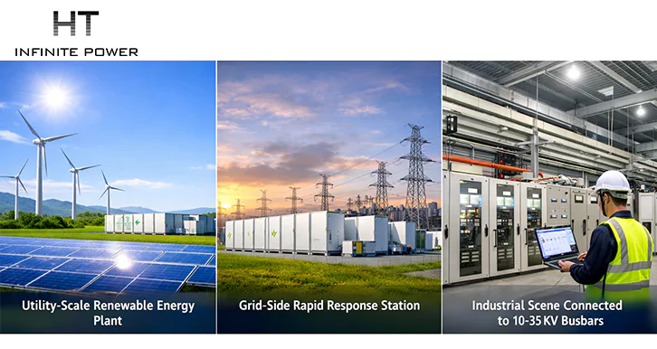
This architecture really shines where the system scale, the response requirement, and the site constraints align:
- Utility-scale renewable farms that want to avoid large transformer banks inside the collection yard.
- Grid-side fast response plants where milliseconds of action are monetized.
- Industrial sites on 10–35 kV buses where space is at a premium and medium-voltage access is native.
It’s less compelling for small installations where the transformer is cheap relative to the engineering effort, or when local grid rules make high-voltage equipment a permitting headache.
What engineers actually do during commissioning
Two test sequences I always insist on before handing over to operations:
1.Staged fault-ride-through tests with utility witness: simulate voltage dips and short injections to demonstrate the inverter’s behavior and to tune relay coordination.
2.Module failover drills: deliberately bypass a module under controlled conditions to validate degraded-mode operation and hot-swap procedures.
Also: log everything with time-synced traces. Post-event analysis is only useful if you can align the inverter controller logs, protection events and SCADA telemetry to the same timestamp. GPS time stamps are cheap insurance.

Designing high-voltage direct-connected PCS is less about swapping hardware and more about rethinking the system boundaries. The transformer wasn’t just a piece of metal; it was part of a protection, insulation and operational posture. Remove it deliberately, with tests and contracts that reflect the new realities: module-level spares, staged utility tests, IMD and PD monitoring, and a procurement mindset that values lifecycle delivered MWh as much as upfront equipment price.
If you execute those trades thoughtfully, you get a plant that is tighter, quicker and more efficient. If you treat direct-connected PCS like a drop-in substitution for a low-voltage inverter plus transformer, the first fault, the first utility witness test or the first poorly matched battery cluster will teach you why the design choices matter.
Why Round-Trip Efficiency Decides the Real Value of Battery Energy Storage
What Qualifies as "Smart" Energy Storage?