High-Voltage Cascaded Energy Storage Systems: Rethinking Large-Scale Grid Storage
2026-05-15
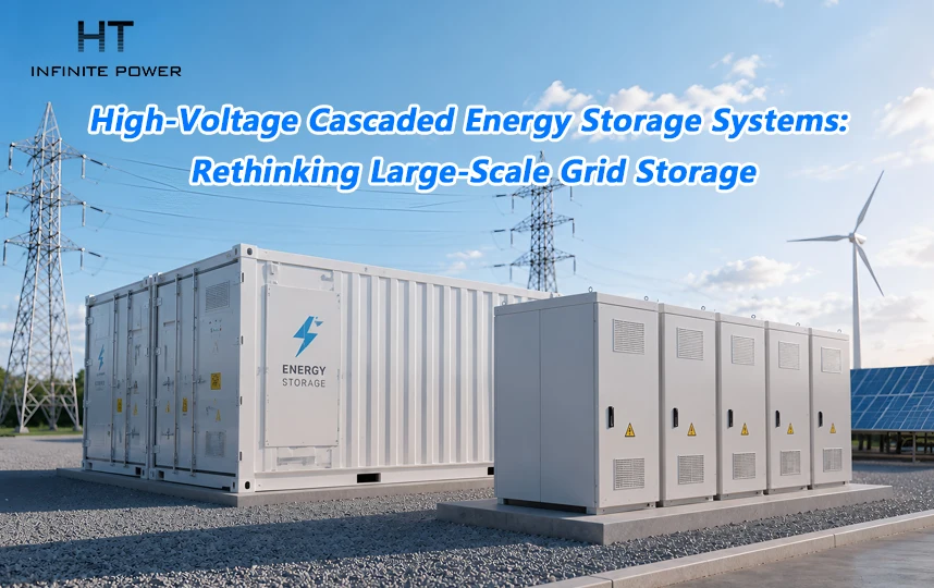
The landscape of utility-scale energy storage has been evolving rapidly, with high-voltage cascaded energy storage systems emerging as a promising alternative to conventional low-voltage solutions. Unlike traditional systems, which rely on a battery cluster feeding a power conversion system (PCS) and then a step-up transformer, the high-voltage cascaded approach bypasses the transformer entirely. This change is not just an engineering curiosity—it fundamentally shifts efficiency, safety, footprint, and reliability metrics for large storage projects.
From Low-Voltage Clusters to Direct High-Voltage Integration
In conventional low-voltage energy storage, multiple battery clusters are connected in parallel, and the output DC is converted to AC through a PCS before being stepped up to grid voltage via a transformer. While proven and widely adopted, this approach presents several challenges: circulating currents, capacity imbalance, transformer losses, and significant spatial requirements.
The high-voltage cascaded system adopts a different philosophy. Batteries are organized into small clusters, each paired with a DC/AC power conversion unit forming a single module. These modules are then connected in series on the AC side, producing direct high-voltage output (6kV, 10kV, 35kV, etc.) suitable for direct grid integration. This architecture eliminates the need for a transformer, reduces system complexity, and enhances overall operational performance.
A single chain segment typically includes:
- A small battery cluster
- A DC/AC H-bridge power unit
Multiple segments are connected across three phases (A, B, C), with star or delta configuration providing high-voltage AC output. The distributed low-voltage clusters increase system safety, reliability, and efficiency, while simplifying maintenance.

Comparing Low-Voltage and High-Voltage Cascaded Solutions
| Dimension | Traditional Low-Voltage Storage | High-Voltage Cascaded Storage |
| Transformer Requirement | Required | Not needed; direct grid connection |
| System Efficiency | ~85–88% (including transformer loss) | ~90–92% (no transformer loss) |
| Footprint | Large (separate transformer, cabling) | 30–40% smaller (highly integrated) |
| Battery Cluster Configuration | Parallel clusters; circulating currents and imbalance | Independent low-voltage clusters; no parallel currents |
| Fault Impact | Single cluster fault may shut down entire stack | Fault module can be bypassed; system derates gracefully |
| Harmonic Performance | Requires additional filters | Output THD <3%; minimal filtering needed |
| Cost Structure | PCS + transformer + battery | PCS integrated with battery; transformer eliminated |
| Voltage Level | Low voltage (400/690V) then stepped up | Directly high voltage (6–35kV) |
This table highlights how high-voltage cascaded systems simplify integration while improving efficiency and operational flexibility.
Key Advantages
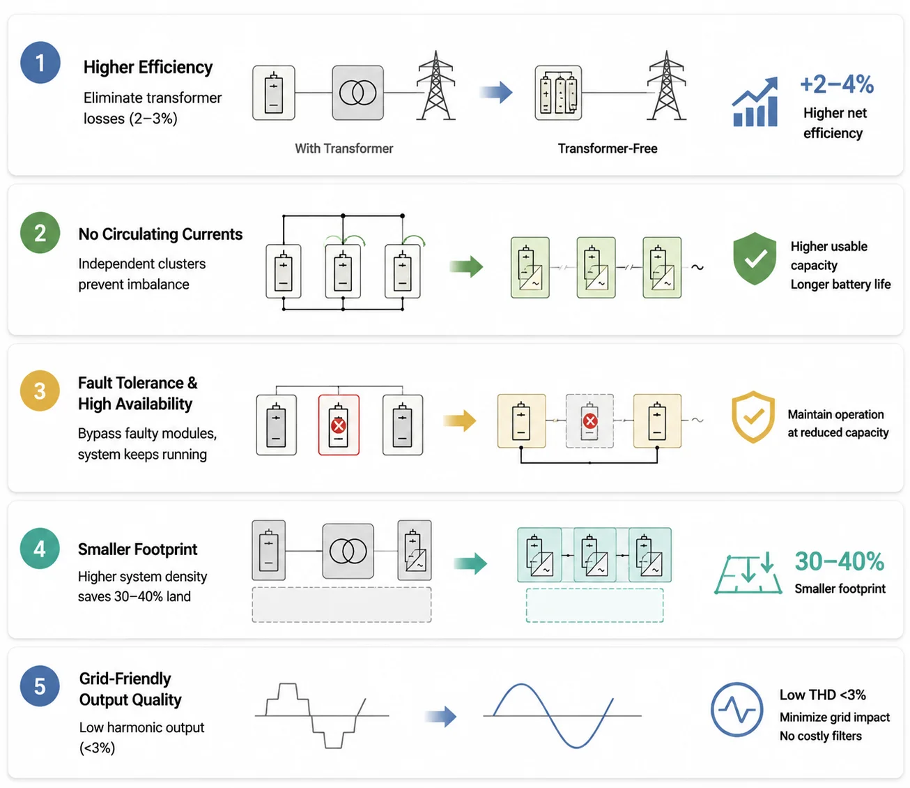
1. Efficiency Gains by Eliminating the Transformer
Transformers introduce 2–3% energy losses. Coupled with high-current losses on the low-voltage side, conventional systems lose significant energy in transmission. By removing the transformer, high-voltage cascaded systems typically increase net efficiency by 2–4%. For 100MW+ storage stations, this translates into substantial annual savings.
2. Independent Battery Clusters Solve Circulating Current Issues
Low-voltage designs with dozens of parallel clusters often suffer from imbalance and the "weakest link" effect. Each high-voltage cascaded module operates independently with its own control system, preventing circulating currents, increasing usable capacity, and extending battery life.
3. Fault Tolerance and High Availability
In conventional systems, a single cluster failure can necessitate taking the entire battery offline. In cascaded designs, faulted modules can be bypassed, allowing the system to continue operation at reduced capacity. This feature is particularly valuable for mission-critical applications such as data centers or industrial facilities.
4. Reduced Footprint
By integrating power units and battery clusters and removing transformers, system density increases, reducing land requirements by 30–40%. This makes high-voltage cascaded systems ideal for urban environments or sites with limited space.
5. Grid-Friendly Output Quality
Using carrier-phase-shift modulation and high equivalent switching frequencies, the system produces low-harmonic AC output (<3%), minimizing grid impact and avoiding costly filtering equipment.
Practical Deployment Scenarios
High-voltage cascaded systems excel in several real-world applications:
| Scenario | Advantage |
| Large standalone storage stations (100MW+) | Efficiency, compact footprint, transformer elimination |
| Thermal-storage combined frequency regulation | Fast response without transformer delay, superior frequency performance |
| Industrial & commercial parks | Space-saving, high efficiency; requires site-specific voltage planning |
| Data centers and high-reliability environments | High availability via modular bypass architecture |
| Retrofitting existing storage | Direct high-voltage integration simplifies upgrade to 6–35kV levels |
These applications demonstrate the versatility of high-voltage cascaded designs across both new installations and upgrades.
Challenges and Limitations
No technology is without constraints. High-voltage cascaded systems require sophisticated control and monitoring:
| Challenge | Explanation |
| System Complexity | Module-level voltage balancing, thermal management, and control are more complex than low-voltage systems |
| BMS Granularity | Each module needs an independent battery management system; monitoring points increase manifold |
| Initial Investment | More power units may raise upfront costs slightly, despite transformer elimination |
| Operation & Maintenance | Requires staff skilled in both high-voltage electrical and power electronics |
| Voltage Compatibility | Best suited for 6–35kV direct grid connection; low-voltage retrofits may be incompatible |
These limitations underscore the need for careful planning and vendor selection, particularly for large-scale industrial applications.
Market Status and Key Players
High-voltage cascaded storage has moved from demonstration to scaled deployment. Leading companies include:
| Company | Key Contribution |
| ZG Energy Storage | Pioneer in 35kV direct-connect systems |
| Jinpan Smart Technology | Integrated high-voltage cascaded storage units (6–35kV) |
| WindSun Science & Technology | Strong PCS technology; excels in mining storage applications |
| NARI Group | Extensive grid-side deployment experience |
| Sungrow | Recent high-voltage cascaded solutions for large-scale deployment |
Adoption is especially pronounced in projects exceeding 100MW, where efficiency, footprint, and response time are critical.
Integrating High-Voltage Cascaded Storage Into Modern Grids
The design philosophy is straightforward: replace large serial battery banks and transformers with distributed low-voltage clusters, integrated PCS modules, and direct high-voltage AC output. The result is a system that is safer, more efficient, and scalable without the usual low-voltage limitations.
For engineers and project managers evaluating storage solutions, the choice can be summarized:
- Low-Voltage Systems: Mature, lower cost, suited for medium-sized installations
- High-Voltage Cascaded Systems: High efficiency, compact, bypasses parallel current issues, ideal for large-scale or high-reliability applications
What is a High-Voltage Direct-Connected PCS?
Understanding Charge and Discharge Rates in Battery Energy Storage Systems