BESS Communication Protocols: How Energy Storage Systems Communicate Internally and Externally
author: HT Infinite Power
2026-11-10
Introduction
A battery energy storage system (BESS) consists of multiple devices that must exchange information to operate as a coordinated system. Battery management systems monitor cell conditions, power conversion systems (PCS) regulate charging and discharging, energy management systems (EMS) coordinate operating strategies, and meters measure electrical parameters at different points of the installation.
These devices cannot operate independently. They need to exchange measurements, operating status, alarms, protection signals, and control commands. The BESS must also communicate with external systems, such as grid dispatch centers, supervisory control platforms, and virtual power plants (VPPs).
Different communication technologies serve different purposes. CAN and Modbus are commonly used for communication between internal devices, while IEC 60870-5-104 and IEC 61850 are frequently considered for communication with grid-related systems. RS-485 provides a physical communication interface, whereas digital input and output (DI/DO) signals support simpler status and control functions.
Understanding these differences is important when designing a BESS communication architecture. Protocol selection affects equipment compatibility, data exchange, control response, system integration, and the ability of the storage system to meet project-specific grid requirements.
This article explains how communication works inside and outside a BESS, which protocols and interfaces are commonly used, how different communication technologies are integrated, and what engineers should consider when selecting a communication solution.
1. How Does Communication Work in a Battery Energy Storage System?
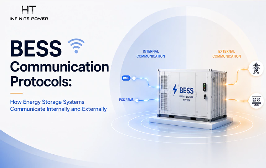
Communication in a BESS can generally be divided into two levels: internal communication and external communication.
Internal communication connects the equipment within the energy storage system. It allows battery controllers, PCS units, meters, environmental monitoring devices, fire protection systems, and EMS platforms to exchange operating information.
External communication connects the BESS to systems outside the installation. These may include grid dispatch centers, distribution network operators, plant-level SCADA systems, VPP platforms, and remote monitoring platforms.
Although the two levels serve different purposes, they are closely connected. Information collected from internal devices is processed by the EMS or a communication gateway before being transmitted to an external platform. In the opposite direction, external operating instructions may be received by the EMS and distributed to the relevant equipment.
Internal Communication: Connecting BESS Equipment
Within a BESS, each device has a specific monitoring or control function.
The battery management system (BMS) monitors battery operating conditions, including cell voltage, temperature, current, and state of charge (SOC). Depending on the system architecture, battery monitoring units may collect cell-level information and transmit it to a battery controller or BMS.
The PCS exchanges information with the BMS and EMS to coordinate charging and discharging. Typical data includes battery operating limits, active power, reactive power, operating status, and fault information.
The EMS collects information from the PCS, BMS, energy meters, and other subsystems. It uses this information to manage charging schedules, power output, operating modes, and energy dispatch according to the project's control strategy.
The following table illustrates common communication relationships in a BESS.
| Equipment connection | Common communication method | Typical information exchanged |
| Battery Monitoring Unit ↔ Battery Controller | CAN | Cell voltage, temperature, sampling data |
| BMS ↔ PCS | CAN or Modbus | SOC, voltage, current, charge/discharge limits, alarms |
| PCS ↔ EMS | Modbus TCP or Modbus RTU | Active/reactive power, operating status, control commands |
| Energy Meter ↔ EMS | Modbus RTU or Modbus TCP | Voltage, current, power, frequency, energy |
| EMS ↔ External Platform | IEC 60870-5-104, IEC 61850, or other project-specific interfaces | Measurements, status, alarms, control commands |
These are typical examples rather than universal requirements. Actual communication methods depend on equipment manufacturers, system architecture, interface availability, and project specifications.
For example, a battery system may use CAN between battery controllers and the BMS, while the PCS communicates with the EMS through Modbus TCP. Another system may use Modbus RTU for certain internal devices. The communication architecture must therefore be confirmed during equipment selection and system integration.
External Communication: Connecting the BESS to Grid and Energy Platforms
External communication allows a BESS to participate in wider power system operations.
For grid-connected projects, the storage system may need to transmit real-time operating information to a grid dispatch center. This can include active power, reactive power, SOC, voltage, current, frequency, operating status, and alarms.
The grid dispatch center may also send operating instructions, such as active power setpoints, reactive power commands, power factor requirements, or other control signals specified by the project.
For VPP applications, communication supports coordinated operation across multiple distributed energy resources. A VPP platform may monitor several storage systems, photovoltaic installations, and other controllable assets. It can aggregate their available capacity and coordinate charging or discharging according to market signals or grid requirements.
The external communication interface must therefore support the data points, control functions, reporting requirements, and response characteristics defined by the project.
2. External Communication Protocols Used in BESS
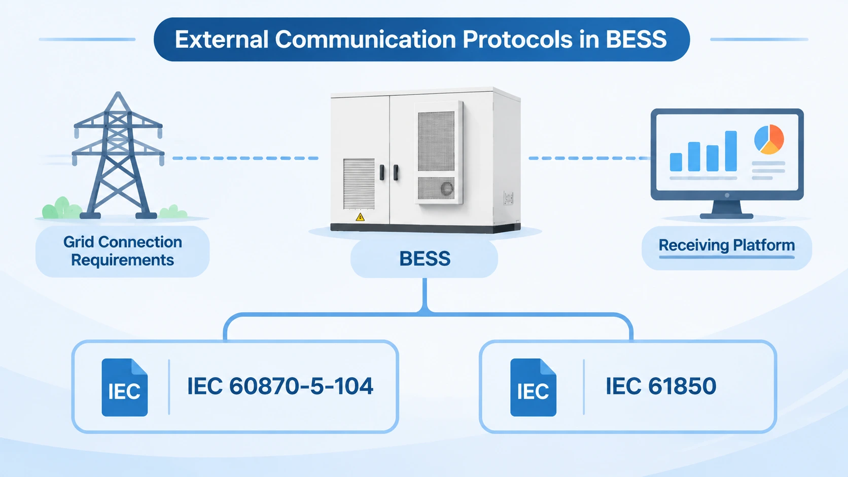
External communication protocols are selected according to grid connection requirements, the receiving platform, and the functions that the energy storage system must perform.
Two important standards in power system applications are IEC 60870-5-104 and IEC 61850. They are not interchangeable in every application, and their use depends on the communication architecture specified for the project.
IEC 60870-5-104: Communication with Grid Dispatch Systems
IEC 60870-5-104, commonly called IEC 104, is a telecontrol communication protocol used in power system monitoring and control.
It operates over TCP/IP networks and is widely used for communication between substations, control centers, and other power system equipment. Its standard TCP port is 2404.
In a BESS project, IEC 104 can provide an interface between the EMS or a communication gateway and an external grid dispatch system.
It operates over TCP/IP networks and is widely used for communication between substations, control centers, and other power system equipment. Its standard TCP port is 2404.
In a BESS project, IEC 104 can provide an interface between the EMS or a communication gateway and an external grid dispatch system.
Typical data exchange includes:
- Telemetry: Active power, reactive power, voltage, current, frequency, SOC, and other measurements.
- Teleindication: Operating states, breaker positions, equipment availability, and alarm information.
- Telecontrol: Remote control commands, such as switching commands or active power setpoints, where supported by the project.
- Teleadjustment: Setpoint adjustments and other operating parameters, depending on the configured control functions.
For example, a grid dispatch center may send an active power command to a BESS through IEC 104. The EMS receives the command, checks whether it is within the permitted operating range, and coordinates the response through the PCS and battery control system.
The actual control sequence depends on the project's control logic, equipment capabilities, and grid requirements. A communication protocol can transmit a command, but it does not independently determine whether the battery system is permitted to execute it.
IEC 104 is therefore commonly considered for projects that require standardized telecontrol communication with grid dispatch systems.
IEC 61850: Communication in Digital Substations and Power Automation Systems
IEC 61850 is a broader communication standard for power utility automation. It defines data models, communication services, and engineering approaches for exchanging information between intelligent electronic devices (IEDs).
In BESS projects, IEC 61850 may be required when the storage system needs to integrate with digital substations, utility automation systems, or other power infrastructure using IEC 61850-based communication.
Three important communication mechanisms associated with IEC 61850 are MMS, GOOSE, and Sampled Values (SV).
MMS (Manufacturing Message Specification)
MMS supports client-server communication between devices and supervisory systems. It is commonly used to access measurements, equipment status, reports, and control-related information.
In a BESS application, an EMS or gateway may use MMS-based communication to exchange operating information with an IEC 61850-compatible substation system.
GOOSE (Generic Object-Oriented Substation Event)
GOOSE supports event-based communication between intelligent electronic devices. It is designed for fast transmission of status changes and event information.
Typical applications include protection-related signals, interlocking, and coordination between substation devices. In a BESS installation, GOOSE may be used when the project requires fast event exchange or protection-related coordination between compatible devices.
SV (Sampled Values)
Sampled Values are used to transmit sampled measurement data, typically current and voltage measurements, in digital substation architectures.
They are particularly relevant to process bus applications in digital substations. Whether SV is required in a BESS project depends on the substation design and measurement architecture.
It is important to distinguish these mechanisms rather than treating IEC 61850 as a single communication function. MMS, GOOSE, and SV serve different purposes, and their performance depends on network design, device implementation, configuration, and the application.
Not every BESS project requires all three. The required IEC 61850 services should be confirmed against the grid connection specification and the interface requirements of the receiving system.
Communication Between BESS and Virtual Power Plants
A virtual power plant aggregates multiple distributed energy resources and coordinates their operation through a central platform.
A BESS connected to a VPP may need to provide information such as:
- Available charging and discharging power
- Current active and reactive power
- SOC and available energy
- Operating status and alarms
- Availability and operational constraints
The VPP may send commands for charging, discharging, or adjusting active power according to its dispatch strategy.
Unlike a conventional grid dispatch interface, VPP communication requirements can vary considerably between platform operators and markets. Some projects use standardized power system protocols, while others rely on vendor-specific APIs or IoT-based communication interfaces.
The communication design should clarify which system is responsible for issuing control commands, how operating limits are enforced, and how conflicting commands are handled. These details are particularly important when the BESS must respond to both local EMS strategies and external dispatch instructions.
3. Internal Communication Protocols Used in BESS
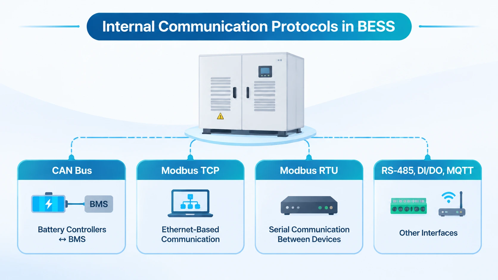
Internal communication technologies connect the different devices within an energy storage system. The choice depends on the amount of data being exchanged, communication distance, response requirements, device interfaces, and the system architecture.
Several technologies commonly appear in BESS designs, but they do not all belong to the same technical category.
CAN Bus: Communication Between Battery Controllers and BMS
Controller Area Network (CAN) is a communication bus widely used in embedded control systems and battery management applications.
In a BESS, CAN is commonly used to exchange information between battery monitoring units, battery controllers, and other compatible control devices.
Typical data includes:
- Cell voltage and temperature information
- Battery voltage and current
- SOC and state of health (SOH)
- Charge and discharge limits
- Battery alarms and protection status
CAN is suitable for communication between distributed control devices that require reliable message exchange.
However, CAN compatibility involves more than simply having a CAN port. Devices must use compatible communication specifications, including message identifiers, data formats, signal definitions, and communication settings.
For battery system integration, the BMS and the connected PCS or battery controller must support compatible data definitions. Otherwise, a physical CAN connection alone will not ensure correct data exchange.
Modbus TCP: Ethernet-Based Device Communication
Modbus TCP is an Ethernet-based implementation of the Modbus application protocol. It is commonly used for communication between the EMS, PCS, energy meters, and other industrial devices.
Compared with serial Modbus communication, Modbus TCP operates over Ethernet networks and uses TCP/IP for data transport.
Typical BESS applications include:
- Reading PCS operating parameters
- Monitoring energy meter measurements
- Exchanging active and reactive power setpoints
- Reading equipment status and alarms
- Communicating with industrial controllers and monitoring systems
For example, the EMS may read active power, reactive power, DC voltage, and operating status from the PCS through Modbus TCP. It can then use this information to coordinate the system's charging and discharging strategy.
Modbus TCP is relatively straightforward to integrate when the connected devices provide compatible register maps and communication settings.
During integration, engineers must verify register addresses, data types, byte order, scaling factors, units, and read/write permissions. Two devices can both support Modbus TCP but still fail to exchange meaningful data if their register definitions differ.
Modbus RTU: Serial Communication Between BESS Devices
Modbus RTU is a serial implementation of the Modbus protocol. It is commonly used for communication between industrial devices over serial interfaces, particularly RS-485.
In a BESS, Modbus RTU may connect energy meters, environmental monitoring devices, power equipment, and other subsystems to the EMS or a communication gateway.
Typical exchanged information includes:
- Voltage and current measurements
- Active and reactive power
- Frequency and power factor
- Energy consumption and generation
- Equipment operating status
A common arrangement uses an RS-485 serial connection with Modbus RTU communication. Multiple devices can share a serial bus when the network topology, device addressing, and electrical requirements are correctly designed.
Compared with Ethernet-based Modbus TCP, Modbus RTU requires attention to serial communication settings, including baud rate, parity, stop bits, and device addresses.
The number of devices, communication distance, polling frequency, and total data volume should also be considered when designing the serial network.
RS-485, DI/DO, and MQTT: Other Communication Interfaces
In addition to CAN and Modbus, BESS installations may use other interfaces and communication technologies.
It is important to distinguish their functions.
It is important to distinguish their functions.
RS-485
RS-485 is an electrical interface standard for serial communication. It defines electrical characteristics rather than an application-level data protocol.
It is commonly used as the physical interface for Modbus RTU communication between the EMS and field devices.
DI/DO (Digital Input and Output)
Digital inputs and outputs are used to exchange simple binary signals between devices.
For example, a BESS may use DI signals to receive external emergency stop status, breaker status, or fire alarm signals. DO signals may be used to transmit equipment status or trigger external control circuits.
DI/DO is useful for straightforward status and control functions, but it does not replace a communication protocol capable of exchanging structured measurements and detailed operating data.
MQTT and IoT Communication
MQTT is a lightweight messaging protocol commonly used in IoT applications. It supports message exchange through a publish-subscribe model.
In BESS projects, MQTT may be used for remote monitoring, cloud-based data collection, and communication with energy management or monitoring platforms.
For example, an EMS or gateway may publish operating data to an MQTT broker, allowing a remote platform to subscribe to the relevant information.
MQTT is not automatically suitable for every grid control application. Its use depends on the project's cybersecurity requirements, network architecture, control responsibilities, and communication performance requirements.
4. How Are Different Communication Protocols Integrated in a BESS?
A BESS rarely relies on only one communication technology. Different devices may use different protocols and interfaces according to their functions and manufacturers.
The EMS or a dedicated communication gateway usually plays an important role in coordinating these connections and making the relevant data available to other systems.
A Typical BESS Communication Architecture
Consider a grid-connected BESS with the following communication arrangement:
- Battery monitoring units communicate with battery controllers through CAN.
- The BMS exchanges battery operating information with the PCS through CAN or another supported interface.
- The PCS communicates with the EMS through Modbus TCP.
- The energy meter communicates with the EMS through Modbus RTU over RS-485.
- The EMS or communication gateway exchanges data with the external grid dispatch system through IEC 60870-5-104.
This is an illustrative architecture, not a mandatory configuration. Actual connections depend on the equipment selected and the communication requirements specified by the project.
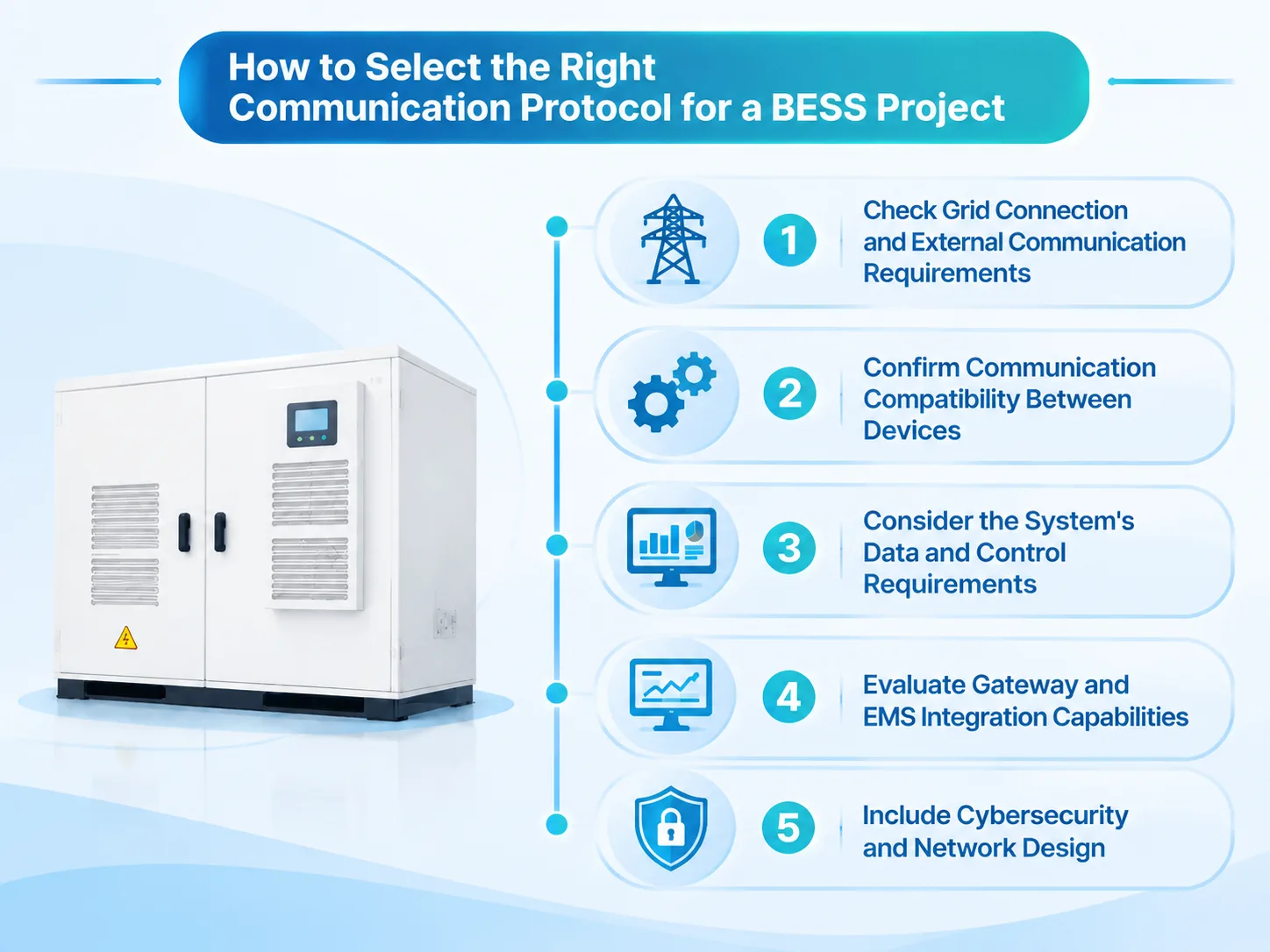
The overall data flow can be understood in three stages.
Stage 1: Data Collection from Internal Devices
The EMS collects operating data from the BMS, PCS, energy meter, and other connected devices.
For example, the BMS provides SOC and battery operating limits, the PCS provides active and reactive power information, and the energy meter provides measurements at the grid connection point.
The EMS uses these inputs to understand the current operating condition of the system.
Stage 2: Data Processing and Protocol Mapping
The EMS or gateway organizes the collected information into a common data model or an external communication format.
This process involves more than converting data from one protocol to another. Engineers must define how each data point is represented and interpreted across the connected systems.
Important mapping parameters include:
- Register or object address: Identifies where the data is located in the source device and where it should appear in the receiving system.
- Data type: Defines whether the value is an integer, floating-point number, Boolean value, or another data format.
- Scaling factor: Determines how raw register values are converted into engineering values.
- Measurement unit: Ensures that values such as kW, kWh, V, A, and percentage are interpreted consistently.
- Data direction: Defines whether the point is read from a device, written to a device, or exchanged in both directions.
- Control permissions: Specifies which system is authorized to issue commands and under what conditions.
- Communication quality and timeout: Determines how missing, delayed, or invalid data is identified and handled.
For example, the PCS may provide active power through a Modbus register. The EMS reads this value, applies the correct data type and scaling factor, and maps it to the corresponding IEC 104 information object for transmission to the grid dispatch center.
If the register is interpreted incorrectly, the external system may receive an incorrect power value even though the physical communication connection is working.
Stage 3: External Data Exchange and Command Execution
After the EMS or gateway has prepared the required data, it transmits measurements, equipment status, and alarms to the external platform through the configured protocol.
Commands received from the external system follow the reverse path. The EMS checks the command against the system's operating limits and control logic before passing the relevant setpoint or instruction to the PCS.
The BMS continues to enforce battery operating constraints. For example, an external charging command does not override the battery's permitted charging current or temperature limits.
This separation of responsibilities is important. The external system provides dispatch instructions, the EMS coordinates system-level operation, and the battery and power conversion control systems enforce their respective equipment limits.
Common Communication Integration Problems
Communication integration problems do not always result from an incorrect cable connection. In many cases, the physical network is operating normally, but the connected devices interpret or process the data differently.
Common problems include:
- Incorrect Modbus register mapping: The EMS reads the wrong register or uses an incorrect address.
- Inconsistent data scaling or units: A value is interpreted using the wrong multiplier or engineering unit.
- CAN communication failure: Battery controllers cannot exchange the required information with the BMS or other connected devices.
- Communication timeout: A device fails to respond within the configured time, resulting in missing or outdated data.
- Incorrect device addressing: Multiple serial devices use conflicting addresses or are configured incorrectly.
- Incompatible protocol implementations: Two devices support the same protocol but use different data definitions, communication settings, or optional functions.
- External communication loss: The EMS or gateway loses its connection to the dispatch center or remote platform.
These problems can cause missing measurements, incorrect equipment status, failed control commands, or interruptions to coordinated system operation.
For this reason, communication testing should cover not only whether devices can connect, but also whether data is correctly interpreted, control commands are executed as intended, and communication failures are detected and handled appropriately.
5. How to Select the Right Communication Protocol for a BESS Project
There is no single communication protocol that is suitable for every BESS installation. The selection should be based on the connected equipment, external interface requirements, control functions, and project operating conditions.
Check Grid Connection and External Communication Requirements
For grid-connected projects, the grid operator or dispatch authority may specify the required communication protocol and data exchange functions.
For example, a project may require IEC 60870-5-104 for telemetry and remote control. Another project involving a digital substation may require IEC 61850 services.
These requirements should be confirmed before selecting the EMS and communication gateway. Otherwise, additional protocol conversion equipment or software development may be necessary during commissioning.
Confirm Communication Compatibility Between Devices
The BMS, PCS, EMS, energy meters, and other devices must support compatible communication interfaces and data definitions.
When evaluating equipment, engineers should confirm:
- Supported communication protocols and physical interfaces
- Communication register maps and data point lists
- Data types, units, and scaling factors
- Read/write permissions and control functions
- Communication settings and network requirements
- Available protocol documentation and integration support
A device that supports Modbus TCP, for example, is not necessarily compatible with every other Modbus TCP device without register mapping and configuration.
Consider the System's Data and Control Requirements
Different communication technologies are suitable for different data exchange requirements.
CAN is commonly used for communication between battery control devices. Modbus TCP and Modbus RTU are widely used for industrial equipment monitoring and control. IEC 104 and IEC 61850 are considered when the project requires communication with grid dispatch or power automation systems.
The selection should account for the amount of data, communication frequency, response requirements, and the number of connected devices.
For applications involving protection or fast event exchange, the project may require specific communication services and network performance. These requirements should be assessed at the system level rather than assumed from the protocol name alone.
Evaluate Gateway and EMS Integration Capabilities
When multiple communication protocols are used, the EMS or gateway must support the required interfaces and data mapping functions.
A suitable integration solution should be able to collect information from different devices, normalize data, map external communication points, and manage control commands.
Engineers should also verify how the system handles communication loss, invalid data, device reconnection, and command conflicts.
These functions are important for projects that combine battery storage with photovoltaic systems, diesel generators, grid connections, or VPP platforms.
Include Cybersecurity and Network Design
Communication design should also consider network segmentation, access control, authentication, and secure remote access.
The BESS may exchange information with internal control devices, plant SCADA systems, grid dispatch centers, and cloud platforms. These connections should not automatically share unrestricted access to the same network.
Network architecture and cybersecurity measures should follow the requirements of the project, the equipment manufacturers, and the relevant grid or industrial control environment.
Conclusion
Communication protocols connect the internal equipment of a BESS and enable the storage system to exchange information with external grid and energy platforms.
Within the system, CAN and Modbus are commonly used for communication between battery controllers, PCS units, meters, and the EMS. For external communication, IEC 60870-5-104 and IEC 61850 may be used according to grid connection and power automation requirements. Other interfaces, including RS-485 and DI/DO, serve supporting communication functions.
Successful integration depends on more than protocol support. Device compatibility, data mapping, control permissions, network design, and communication fault handling all affect whether information can be exchanged and interpreted correctly.
For BESS projects, these requirements should be addressed during equipment selection and system engineering rather than left until commissioning. A well-designed communication architecture helps the storage system coordinate its internal devices, respond to external operating instructions, and integrate reliably with the wider power system.
Frequently Asked Questions
Which communication protocols are commonly used in battery energy storage systems?
Commonly used communication technologies include CAN, Modbus TCP, Modbus RTU, IEC 60870-5-104, and IEC 61850. RS-485 is frequently used as a serial communication interface, while DI/DO signals support simple status and control functions. MQTT may also be used for remote monitoring and IoT-based data exchange.
The actual combination depends on the BESS architecture and project requirements.
The actual combination depends on the BESS architecture and project requirements.
What is the difference between Modbus TCP and Modbus RTU in a BESS?
Modbus TCP uses Ethernet and TCP/IP for communication, while Modbus RTU uses serial communication, commonly over RS-485.
Modbus TCP is often used for communication between the EMS and Ethernet-enabled devices such as PCS units. Modbus RTU is commonly used for energy meters and other field devices with serial interfaces.
Both can exchange measurements, operating status, and supported control commands, provided the devices have compatible data definitions.
Modbus TCP is often used for communication between the EMS and Ethernet-enabled devices such as PCS units. Modbus RTU is commonly used for energy meters and other field devices with serial interfaces.
Both can exchange measurements, operating status, and supported control commands, provided the devices have compatible data definitions.
What is the difference between IEC 104 and IEC 61850?
IEC 60870-5-104 is a telecontrol protocol commonly used for communication between control centers and power system equipment.
IEC 61850 is a broader power utility automation standard that defines data models and communication services. Its MMS, GOOSE, and SV mechanisms support different applications, including supervisory data exchange, event-based communication, and sampled measurement transmission.
The appropriate standard depends on the grid connection and substation communication requirements.
IEC 61850 is a broader power utility automation standard that defines data models and communication services. Its MMS, GOOSE, and SV mechanisms support different applications, including supervisory data exchange, event-based communication, and sampled measurement transmission.
The appropriate standard depends on the grid connection and substation communication requirements.
Can a BESS use multiple communication protocols at the same time?
Yes. A BESS commonly uses multiple communication technologies because different devices have different interface requirements.
For example, battery controllers may use CAN, the PCS may communicate with the EMS through Modbus TCP, and the EMS may exchange information with a grid dispatch center through IEC 104.
The EMS or a communication gateway coordinates the data exchange and protocol mapping between these systems.
Is RS-485 a communication protocol?
No. RS-485 is an electrical interface standard that defines the electrical characteristics of serial communication.
It is commonly used as the physical interface for protocols such as Modbus RTU. The interface defines how signals are transmitted electrically, while the communication protocol defines how data is structured and exchanged.
Does every BESS project need IEC 61850?
No. IEC 61850 is required only when specified by the project or needed for integration with compatible power automation systems, such as digital substations.
Many BESS projects use IEC 104 or other interfaces for external communication. The required protocol should be confirmed with the grid operator and the receiving system during the engineering design stage.
Low Battery Problems in Energy Storage Systems: Common Causes and Solutions
Related Article