What Is Real, Reactive and Apparent Power?
2026-01-23

Engineers talk about kilowatts, kilovolt-amps and kilovolt-ampere reactive the way drivers talk about speed, fuel and engine torque — they’re related, but not the same thing. Confusing these three can lead to oversized transformers, surprise utility penalties, unhappy motors, and mis-sized inverters. This article explains, step-by-step and with real numbers, what real, reactive and apparent power actually are, why they matter in practice, and how to compute and correct them on real systems.
A short, practical definition up front
- Real power (P, measured in kW) — the power that performs useful work: turns motors, heats ovens, runs servers. It is the time-average of instantaneous voltage × current in phase.
- Reactive power (Q, measured in kVAR) — the power that oscillates between source and reactive elements (inductors, capacitors). It doesn’t do net work but is necessary to establish magnetic fields in motors or voltage support in networks.
- Apparent power (S, measured in kVA) — the vector combination of real and reactive power; the product of RMS voltage and RMS current (S = V × I). It represents the total “electrical stress” on conductors and transformers.
They are related by the familiar vector relation:
and by the power-factor (PF):
where φ is the phase angle between voltage and curent.

Why this matters in the real world
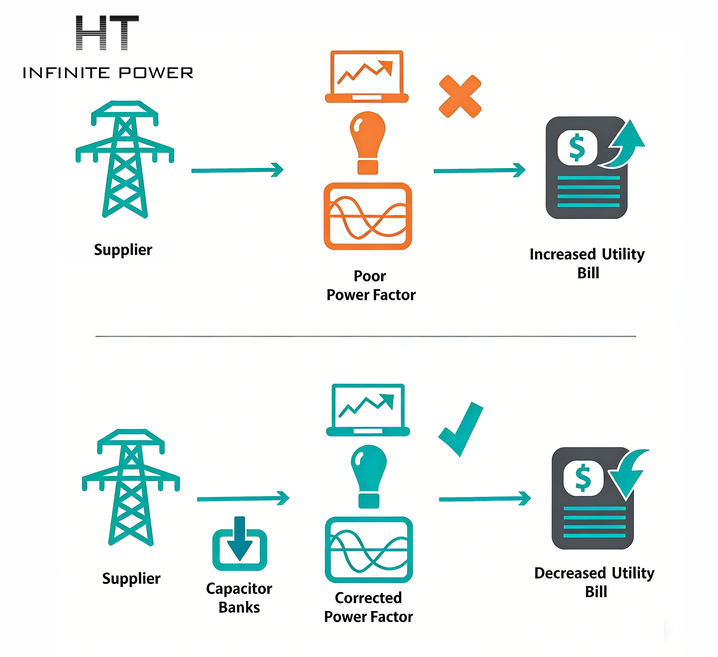
Real power is what you buy by the kWh. Apparent power determines the size of cables, transformers and inverters — they must carry the current. Reactive power can force bigger equipment and cause extra losses and voltage drops even though it doesn’t show up as energy consumption. Utilities may bill you for poor power factor or charge demand on kVA, not just kW. For plant designers, confusing kW and kVA is the fastest way to under-spec a transformer or overpay for distribution upgrades.
A concrete single-phase example (step-by-step)
Suppose you have a 10 kW resistive heater that, because of some upstream inductance, exhibits a power factor of 0.8 lagging. What are Q and S?
1.Real power
2.Power factor
3.Reactive power using tangent:
So
4.Apparent power
Interpretation: the site must provide 12.5 kVA of transformer/inverter capacity to serve 10 kW of useful load because 7.5 kVAR must circulate.
A three-phase industrial example — careful arithmetic
A plant has a 500 kW load at 400 V line-to-line, power factor 0.95 lagging. What line current flows and how much reactive power is present?
1.Given:
2.First compute phase angle:
3.Calculate three-phase line current using:
Compute denominator step-by-step:
- Multiply:1.7320508076×400=692.82032304.
- Multiply by PF:692.82032304×0.95=658.179306888.
Now current:
Compute denominator step-by-step:~760 A per line.
4.Reactive power:
5.Apparent power:
These numbers show: although the plant needs 500 kW of real power, the transformer and cables must be sized for roughly 526 kVA, carrying ~760 A line current.
Power-factor correction — a practical capacitor sizing example
If your 100 kW motor bank operates at PF 0.80 lagging and you want to raise PF to 0.98, how much capacitance (kVAR) is needed?
1.Initial:
2.Desired:
So you’d specify a ~55 kVAR capacitor bank (plus a margin and detuning if harmonics exist). This reduces apparent power and line current, shrinking transformer loading and loss.
Leading vs lagging, harmonics and operational cautions
- Inductive loads (motors, reactors) cause lagging reactive power (current lags voltage).
-
Capacitive loads (power-factor correction caps, some electronics) cause leading reactive power (current leads voltage).
- Overcompensating with capacitors can cause voltage rise or resonance with network inductance — never add large static banks without harmonic and resonance analysis (detuned filters or active harmonic filters are common measures).
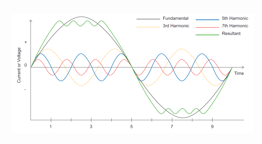
Modern power electronics (VFDs, UPS, chargers) introduce harmonics. Simple capacitor banks tuned to 5th/7th harmonic frequencies can amplify distortion; in practice, detuned reactors or active harmonic filters are used.
Measurement and metering — how you actually see these quantities
Modern power meters report P, Q, S and PF directly, usually per phase and in totals. For capacitive/inductive identification, pay attention to sign conventions: utilities often state kVAR positive for lagging (inductive) and negative for leading (capacitive), but standards vary — confirm with your meter’s documentation.
Practical impacts on system design
- Transformer sizing: specify in kVA not kW. Always size for the worst-case apparent power including harmonic derating.
- Cable heating: heating depends on RMS current (I^2R); apparent power determines heating even if real power is modest.
- Utility billing: many utilities penalize low PF or bill demand in kVA; improving PF can reduce monthly bills even if energy use (kWh) is unchanged.
- Inverter selection: for battery and PV systems, select inverters and switchgear rated for required kVA and short-time overloads if reactive support is expected.
A short industrial case study (synthesized, practical)
A mid-sized food processing plant reported high monthly demand charges and frequent nuisance trips during compressor starts. Investigation revealed a sustained plant PF of ~0.78 lagging, with large motor inrushes and a distribution transformer running at 95% of nameplate kVA. Solution path:
1.Install a staged capacitor bank sized to correct bulk PF to ~0.96 during typical loads (calculated kVAR ~350 kVAR).
2.Add detuned filters to avoid 5th harmonic amplification from VFDs.
3.Implement soft-start schemes for compressors and stagger starts to reduce inrush peaks.
4.Post-deployment, transformer loading fell to 75% nameplate and demand charges dropped by ~15% — ROI under three years.
Lessons: PF correction must be combined with operational fixes and harmonic mitigation for reliable results.
Final practical checklist (what to do next)
- Measure: collect 15-minute logged P, Q, S and PF for at least 1 month.
- Calculate: derive average PF, peak kVA, and identify worst-case concurrent loads.
- Size: select transformer/inverter/cable based on kVA, not kW.
- Correct: size capacitor banks using the Q difference method shown above; include detuning if harmonics exist.
- Verify: require FAT/SAT logs and have an on-site harmonic scan after installation.
- Contract: specify vendor guarantees for THD limits and PF improvement; include remediation clauses.
What Is Superconducting Magnetic Energy Storage (SMES)?
What Is Grid-Forming vs Grid-Following Control?