What Is MVDC (Medium-Voltage DC) and Where Is It Used?
2026-02-06
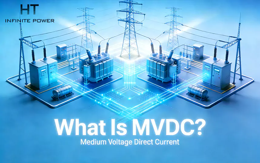
If you’ve wired a building, you think in volts, breakers and breakers tripping. If you’ve designed a power electronic inverter bank, you think in semiconductor limits and switching harmonics. MVDC sits in the middle of those worlds and quietly rewrites a few rules. Medium-Voltage DC—typically DC distribution in the kilovolt range instead of the low-voltage 400/480 V level—lets engineers move megawatts with far lower currents, fewer conversion stages for certain systems, and new ways to manage resilience and efficiency.
This article explains MVDC in practical terms: what it is, why it matters, how it’s built, the real engineering trade-offs, protection and safety implications, and where people actually use it today (or should be thinking about it). I’ll mix intuition, short calculations you can reproduce, architecture options and field examples so you can judge whether MVDC belongs in your next project.
This article explains MVDC in practical terms: what it is, why it matters, how it’s built, the real engineering trade-offs, protection and safety implications, and where people actually use it today (or should be thinking about it). I’ll mix intuition, short calculations you can reproduce, architecture options and field examples so you can judge whether MVDC belongs in your next project.
1.What exactly do we mean by MVDC?
“Medium-voltage” is a fuzzy range because standards and regions disagree slightly, but for the purpose of practical engineering discussion MVDC usually means DC distribution at roughly 1 kV to 35 kV. It’s above typical low-voltage DC (LVDC) systems (e.g., 380–1,000 VDC) and below transmission HVDC megavolt links. MVDC is the sweet spot for distributing multi-MW power within campuses, industrial parks, ships, offshore platforms and large microgrids.
Why use DC at this level? The simple answer: power = voltage × current. For a fixed power transfer, higher DC voltage means lower conductor current, smaller copper cross-sections or reduced I²R loss. But the story is not only about lower current—MVDC changes the number of conversions, the kinds of protection devices you need, how you interact with the AC grid, and which services you can provide cheaply and quickly.
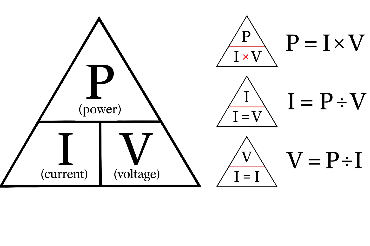
2.The basic arithmetic that makes MVDC interesting
Engineers love numbers. Let’s make one quick, practical calculation to fix intuition.
Example: You need to deliver 2 MW to a load.
Example: You need to deliver 2 MW to a load.
- At 1,000 V DC: I = P / V = 2,000 kW / 1 kV = 2,000 A.
- At 10,000 V DC: I = 2,000 kW / 10 kV = 200 A.
Two observations:
(1).Moving from 1 kV to 10 kV reduces conductor current by a factor of 10, which dramatically lowers copper losses (I²R) and conductor size.
(2).Lower current reduces thermal stress and allows more compact cable runs for the same power.
(2).Lower current reduces thermal stress and allows more compact cable runs for the same power.
Loss comparison (simplified): If conductor resistance is R, losses scale as I²R. At 10 kV the loss is (200/2000)² = (0.1)² = 0.01 → 1% of the loss at 1 kV for the same R. In practice R differs with conductor size, but the point stands: raising voltage is an efficient lever.
However, higher DC voltage raises insulation requirements, creepage distances, and demands robust DC circuit breakers and converter hardware. That’s the trade-off: material and equipment complexity versus conductor and loss savings.
3.Why battery energy storage systems (BESS) are a natural fit for MVDC
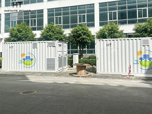
This is an important practical point that engineers and procurement teams ask early: if you are planning MVDC, batteries are not an afterthought—they are often the central anchor.
Because batteries are inherently DC sources and sinks, pairing a centralized BESS with an MVDC backbone reduces conversion stages (fewer AC ↔ DC transitions), shortens response time for high-power events, and improves overall round-trip efficiency. In many multi-megawatt applications—microgrids, data centers, EV charging hubs and industrial parks—the BESS serves three key MVDC roles:
- Energy anchor: a centralized BESS provides steady energy and headroom so converters can operate in their optimal band; it also lets MVDC islands exchange energy without multiple AC conversions.
- Fast buffer: for sub-second to multi-second transients (motor starts, charger inrush, AI rack spikes), BESS on MVDC injects power almost instantaneously with minimal converter latency.
- Protection & ride-through support: during upstream AC disturbances, a BESS on MVDC can absorb or inject energy to keep local converters stable, acting as a virtual inertia resource and reducing the stress on DC breakers and protection schemes.
Practical consequence: when you evaluate MVDC for a site, size the BESS early in the trade studies—not as an after-install. The economics of conductor savings and conversion-stage elimination often depend on having a centralized BESS with rated power and SOC headroom to perform these duties.
4.MVDC architectures — how people actually implement it
There are a few ways MVDC systems are assembled in the field. They differ by the topology of DC buses, converter choices, grounding schemes and whether AC is still present at the load.
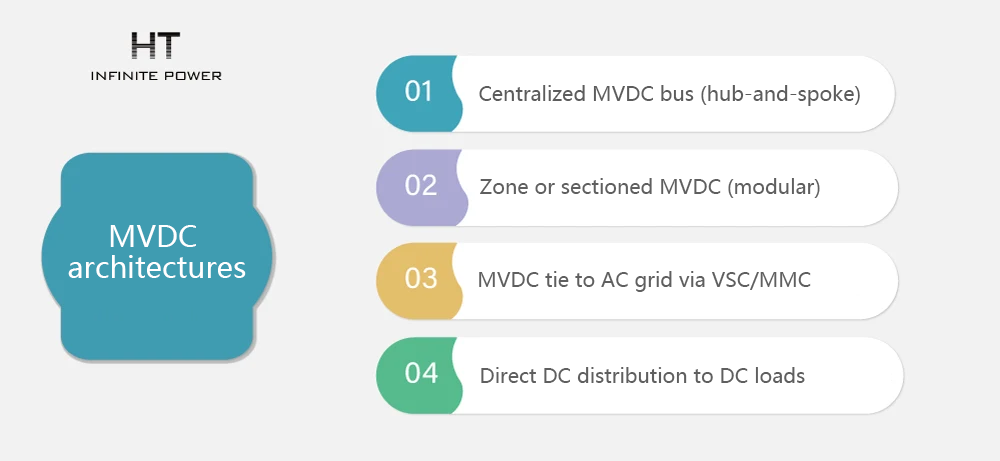
a)Centralized MVDC bus (hub-and-spoke)
One big DC bus at medium voltage, with multiple injection and extraction points (rectifiers, inverters, active filters). Good for campus or platform-level distribution where many loads sit within a shared DC zone. Pros: simplified sharing of energy, easy to route power between domains. Cons: single bus protection becomes critical.
BESS role: a centralized BESS typically connects near the hub, enabling efficient energy exchange and providing the main buffering capability that lets smaller local converters operate without large DC bus fluctuations.
BESS role: a centralized BESS typically connects near the hub, enabling efficient energy exchange and providing the main buffering capability that lets smaller local converters operate without large DC bus fluctuations.
b)Zone or sectioned MVDC (modular)
Multiple DC islands (each a container or room) with local DC bus and inter-tie switches. This supports staged expansion and localized protection. More flexible for incremental deployments.
BESS role: distributed BESS modules can be colocated with each zone to reduce fault energy per segment and enable staged commissioning.
BESS role: distributed BESS modules can be colocated with each zone to reduce fault energy per segment and enable staged commissioning.
c)MVDC tie to AC grid via VSC/MMC
Converters interface the MVDC bus to the AC grid. Modern approaches use Voltage-Source Converters (VSC) or Modular Multilevel Converters (MMC) rated for MVDC. These converters are the heart of MVDC systems and determine how smoothly the DC world interacts with the AC grid.
BESS role: the BESS DC link reduces the number of AC conversion cycles when charging from PV or discharging to AC, improving round-trip efficiency. BESS sizing and converter ratings must be coordinated.
d)Direct DC distribution to DC loads
Some industrial loads (electrolysers, traction, large rectifier-fed systems) can accept DC directly. If the load is DC-native, you can skip an AC conversion stage and improve overall efficiency.
BESS role: when loads are DC-native, colocated BESS allows immediate injection or absorption of power without AC intermediaries, simplifying control and improving responsiveness.
5. Conversion technology and the role of power electronics
You can’t run an MVDC system without converters—either to charge the DC bus from AC, to feed AC loads from DC, or to transfer power between DC islands. The converter landscape is evolving rapidly:
- Line-side converters / rectifiers: convert utility AC to MVDC. Traditionally bulky, but advances in high-voltage modular converters make compact solutions feasible.
- Voltage-Source Converters (VSCs): bidirectional devices that regulate MVDC and support functions like reactive power through coordinated control.
- Modular Multilevel Converters (MMC): scale well to high voltages and megawatt powers with lower harmonic content. MMCs make MVDC-to-AC conversion realistic and efficien
- DC-DC converters: step MVDC up or down, isolate islands, or provide regulated outputs to LVDC buses.
Converter choice matters because it drives harmonics, control complexity, cost, and protection needs. If you plan MVDC, get serious about converter thermal ratings, short-time overload, and fault ride-through behavior. Also ensure the converters’ control strategies coordinate with the BESS EMS/EMS (Energy Management System) to avoid conflicting dispatch commands during transient events.
6.Protection, DC breakers and fault handling — the main practical headache
AC protection relies heavily on zero crossings: breakers can interrupt at a zero current moment, and relays detect phase angles and frequency. DC has no periodic zero crossing, so interrupting DC fault currents is hard. That’s why DC circuit breakers (mechanical, hybrid, or solid-state) and fast protection coordination become central to MVDC viability.
Key protection considerations:
- Fault detection: DC faults escalate quickly. Detection needs high sampling rates and robust algorithms for directional detection.
- Breaker technology: hybrid DC breakers combine fast semiconductor interruption with mechanical contacts to offload energy and reduce losses. They are expensive but necessary for credible MVDC networks.
- Segmented isolation: designing the network to isolate small sections minimizes energy to be interrupted and improves selectivity.
- Grounding/neutral strategy: full DC isolation, midpoint grounding, or negative grounding—each has implications for overvoltages and insulation design.
- Coordination with converters and BESS: converters and battery inverters must be able to detect and cooperate with breakers—BESS can help by rapidly reducing local DC bus current during faults if coordinated.
In short: protection is not a detail you add later. It’s the core engineering driver for MVDC cost and layout.
7.Thermal & insulation design, and safety
MVDC raises the bar on electrical insulation. Under DC stress, aging mechanisms (partial discharge, surface tracking) behave differently than AC. Enclosures, cable terminations, connectors and surge protection must be rated for DC voltages and continuous stress.
Safety protocols also change: maintenance on MVDC systems requires strict isolation practices, access control, and detailed arc-flash studies (DC arcs behave differently). Human factors—how operators perceive risk—can be a limiting factor to adoption; thoughtful human-centered design and training are essential.
Again, BESS integration affects these choices: battery terminals and DC busbars need compatible insulation and safe disconnects; quench or fault modes for batteries must be part of maintenance procedures.
8.Efficiency & energy flow — where MVDC saves energy
Beyond conductor and I²R savings, MVDC can reduce conversion stages. Consider a renewable plant with PV + battery + DC loads:
- In a conventional AC-centric layout: PV → inverter to AC → distribution → inverter/rectifier at load → DC load. Each stage is an efficiency hit.
- In an MVDC-centric layout: PV (DC) → DC bus → DC-DC to loads or converters only when AC is needed. Fewer inversions → higher system round-trip efficiency.
Another win: for short-duration buffering (fast frequency response, EV charging peaks), MVDC allows batteries to inject power with minimal intermediate conversions, improving response time and lowering losses. When a BESS is part of the MVDC backbone, the efficiency and response improvements are most pronounced — and the BESS can be sized and controlled specifically to support transient events without unnecessary cycling.
9.Where is MVDC being used today — practical applications
MVDC is not a theoretical idea — real projects and sectors are adopting it.
a)Offshore wind and subsea arrays
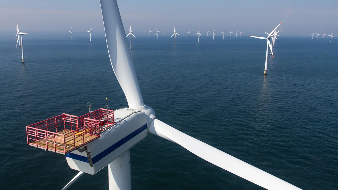
Wind turbines produce DC at times during internal conversions, and MVDC collector systems can aggregate generation with fewer conversions and lower losses before AC export. Additionally, HVDC export is common; MVDC acts as an intermediate aggregation layer offshore.
BESS role: offshore substations increasingly consider BESS for smoothing and immediate dispatch, buffering turbine transients and facilitating coordinated export control
BESS role: offshore substations increasingly consider BESS for smoothing and immediate dispatch, buffering turbine transients and facilitating coordinated export control
b)All-electric ships and naval vessels
Ships increasingly use electric propulsion and large power loads (radar, weapons, hotel loads). MVDC simplifies distribution aboard with weight and cabling benefits, and supports fast energy routing between propulsion, hotel loads and energy storage.
BESS role: onboard batteries (or supercapacitor hybrids) provide immediate power for propulsion bursts and reduce generator cycling, while MVDC routes power efficiently across the vessel.
BESS role: onboard batteries (or supercapacitor hybrids) provide immediate power for propulsion bursts and reduce generator cycling, while MVDC routes power efficiently across the vessel.
c) Large data centers and AIDC-ready sites
Data centers (especially AI data centers with very high rack power density) can benefit from MVDC by reducing conversion losses and bringing higher reliability for DC-native equipment. Note: this is emerging—deployments are pilot in many cases.
BESS role: A centralized MVDC BESS can be the site’s primary UPS and energy-shifting device, enabling millisecond ride-through for AI racks and peak shaving for cost control with fewer conversions.
BESS role: A centralized MVDC BESS can be the site’s primary UPS and energy-shifting device, enabling millisecond ride-through for AI racks and peak shaving for cost control with fewer conversions.
d) Industrial plants and mining
Heavy DC loads (electrolysers, smelters, large DC drives) and remote mines with long cable runs can use MVDC to cut losses and simplify distribution.
BESS role: colocated BESS supplies buffering for large DC loads and can be used to reduce genset wear by handling transients.
BESS role: colocated BESS supplies buffering for large DC loads and can be used to reduce genset wear by handling transients.
e) Microgrids, campus and district energy systems
For campuses with renewables, storage and combined heat & power, MVDC can streamline energy sharing and support islanding with fewer losses.
BESS role: the BESS becomes the energy anchor, enabling fast islanding and smoothing interactions with distributed generation.
BESS role: the BESS becomes the energy anchor, enabling fast islanding and smoothing interactions with distributed generation.
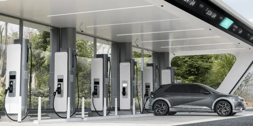
f) EV fast-charging hubs
High-power fast-charging requires multi-MW provisioning. MVDC can centralize battery buffering and distribute power to chargers with small conductor sizes and reduced losses.
BESS role: MVDC-fed BESS banks buffer grid supply, reduce demand charges and deliver the peak power that chargers require without massive grid upgrades.
BESS role: MVDC-fed BESS banks buffer grid supply, reduce demand charges and deliver the peak power that chargers require without massive grid upgrades.
10.Practical design trade-offs and when NOT to use MVDC
MVDC is not a silver bullet. Consider these cases where AC is still preferable:
- Small installations (< a few hundred kW): the converter and breaker overhead is hard to justify.
- Ecosystems dominated by AC loads with no DC-native equipment: conversion savings are small.
- Environments with immature DC protection or no local service expertise: O&M risk rises.
- Sites where standards or regulators mandate AC distribution: permitting friction can delay projects.
Use MVDC when power scale, cable length, or conversion count create real measurable savings that outweigh capital and operational complexity.
11. Example design case — MVDC for a 5 MW campus
A short, reproducible sketch to keep intuition practical.
Requirement: Supply a 5 MW peak campus with several high-density loads; aim to reduce cable bulk and support a 2 MW battery buffer for fast peak shaving.
Design choices:
- Bus voltage: choose 5 kV DC as compromise between insulation and conductor savings.
- Peak current at 5 kV: 5,000 kW / 5 kV = 1,000 A. Compare to 1 kV → 5,000 A.
- Use modular MMC converters rated 5 kV for AC coupling at the substation and LVDC/AC converters at local clusters.
- Segment the MVDC bus into 3 zones with fast hybrid DC breakers to limit fault energy.
- Reserve 10–20% SOC headroom in the 2 MW BESS to support converter ride-through and fast response.
Expected benefits:
-
Cable cross-section reduction ~ 3–6× depending on distance and bundling.
- Lower I²R losses during peak transfers.
- Faster, fewer conversions for DC loads offering 1–3% system efficiency improvement—material when energy bills are large.
This sketch isn’t a finished design, but it’s the kind of back-of-envelope sizing you can do in 15 minutes to validate whether MVDC is worth deeper study.
12.Standards, testing and commissioning — what to require
MVDC projects must insist on rigorous FAT/SAT testing and vendor evidence for components:
- Converter test logs for MVDC operation modes (steady state, transients, fault injection).
- DC breaker performance: interruption capacity, peak energy absorption and reclose behavior.
- Protection coordination studies: show selectivity and clearing times for DC faults.
- Insulation and partial-discharge tests on cables and terminations.
- EMC and harmonic studies because DC systems interact differently with power electronics.
In procurement, specify test traces with timestamps, repeatable black-start drills for microgrids and clear O&M handover where maintenance teams can practice safe isolation.
13. The road ahead — trends and what will change adoption
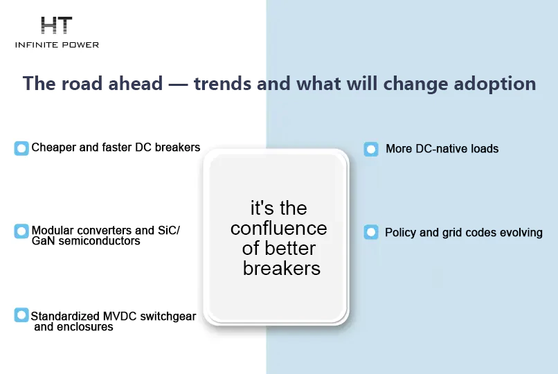
Several technological trends and market factors will shape MVDC uptake:
- Cheaper and faster DC breakers: as solid-state and hybrid breakers get cheaper, safety and selectivity improve.
- Modular converters and SiC/GaN semiconductors reduce converter losses and size at MV voltages.
- Standardized MVDC switchgear and enclosures will lower engineering and permitting friction.
- More DC-native loads (data centers, electrolyzers, chargers) increase MVDC’s value proposition.
- Policy and grid codes evolving to recognize DC distribution use cases will accelerate adoption.
The tipping point is not a single invention—it's the confluence of better breakers, cheaper semiconductors, and more DC-friendly loads.
14.Practical checklist for considering MVDC on your project
(1).Collect load profiles (15-minute or faster), identify peak power and distribution distances.
(2).Model energy and losses for LVDC vs MVDC vs AC options across the expected lifetime (include conversion losses and breaker/maintenance costs).
(3).Map DC-native loads and assess how many conversion stages you can eliminate.
(4).Demand vendor proof: converter MMC/VSC logs, DC breaker specs, and FAT/SAT records.
(5).Design for segmentation: minimize energy per fault by creating small isolation zones with fast breakers.
(6).Staff readiness: ensure O&M teams and safety procedures are in place.
(7).Engage regulators early: permitting for DC may require extra demonstration in some jurisdictions.
(2).Model energy and losses for LVDC vs MVDC vs AC options across the expected lifetime (include conversion losses and breaker/maintenance costs).
(3).Map DC-native loads and assess how many conversion stages you can eliminate.
(4).Demand vendor proof: converter MMC/VSC logs, DC breaker specs, and FAT/SAT records.
(5).Design for segmentation: minimize energy per fault by creating small isolation zones with fast breakers.
(6).Staff readiness: ensure O&M teams and safety procedures are in place.
(7).Engage regulators early: permitting for DC may require extra demonstration in some jurisdictions.
What Qualifies as "Smart" Energy Storage?
AI Data Centers and the Transformation of the Energy Storage Industry