Energy Storage Battery PACK: Understanding the Core of Energy Storage Technology
2025-12-11
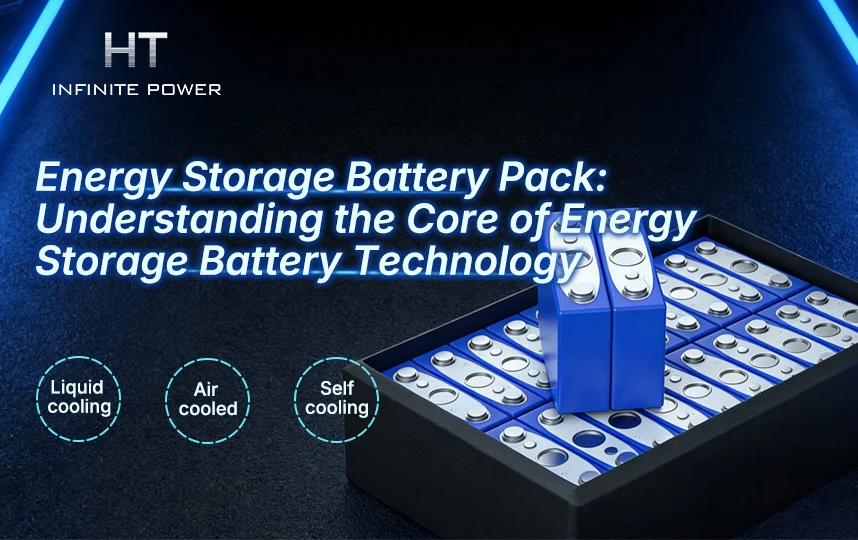
Common battery PACKs are generally classified into three cooling methods: liquid cooling, air cooling, and natural cooling. Battery cells are sensitive to temperature, with an optimal operating range of 15–35°C. Temperature variations can cause different degrees of capacity loss in lithium batteries. Specifically, the usable capacity is approximately 70% at –10°C, 85% at 0°C, and 100% at 25°C. Among the three cooling methods, natural cooling has slow heat dissipation, low efficiency, and poor temperature control, which does not meet the cooling requirements of large-capacity energy storage systems. As a result, liquid-cooled PACKs dominate the current energy storage market.
Before diving deeper into battery PACKs, it is helpful to understand the concepts of cell, battery module, and battery pack (PACK).
Battery Cell (Cell)
A battery cell is the fundamental unit of a battery, forming the core component of both battery modules and battery packs (PACKs). Typically, a single cell provides a voltage between 3 V and 4 V. It is a sealed, independent unit that connects the positive and negative electrodes, usually made from lithium-ion, nickel-metal hydride, or lead-acid materials. A cell consists of a positive electrode, a negative electrode, and separators to prevent direct electrical contact between the two electrodes.
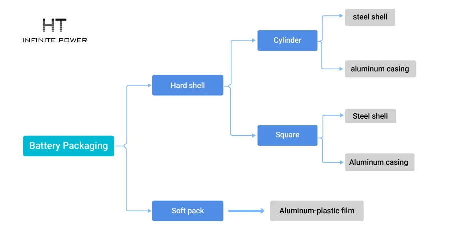
For lithium-ion cells, packaging mainly falls into two categories based on the casing: hard shell and pouch. Hard-shell cells are typically made of steel or aluminum and can be further divided into cylindrical and prismatic types depending on the arrangement of the electrodes. Pouch cells generally use aluminum-plastic film packaging. With advancements in packaging technology, cylindrical, prismatic, and pouch cells have gradually become the three dominant forms.
These three packaging types correspond to different electrode winding methods: cylindrical lithium-ion cells use cylindrical winding, prismatic cells use prismatic winding, and pouch cells use stacked prismatic layers.
Cylindrical cells offer high production efficiency and lower manufacturing costs but have relatively lower energy density per cell and lower inherent safety.
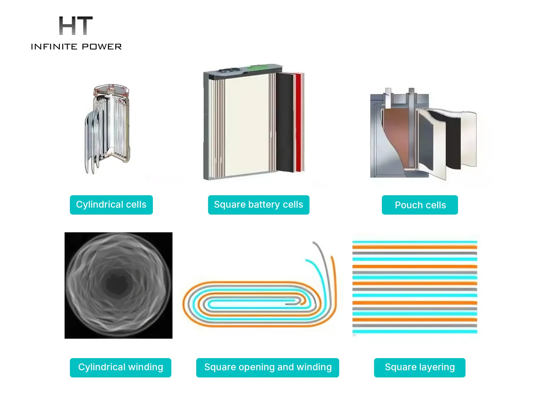
Pouch cells use aluminum-plastic film packaging, offering better safety, lighter weight compared with steel or aluminum cases, higher specific energy, lower internal resistance, and longer cycle life. However, they face challenges such as numerous sizes, lower automation, slower production efficiency, higher cost, dependence on imported high-end materials, and less consistency.
Battery Module (Batteries)
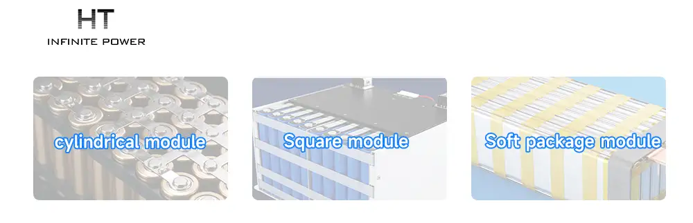
A battery module is a single physical unit composed of multiple cells. It provides higher voltage and capacity than an individual cell. For example, a module may connect four cells in series to deliver a nominal voltage of 12 V, or connect multiple cells in parallel to achieve greater capacity.
Battery Pack (PACK)
A battery pack is generally composed of multiple battery modules and is equipped with a Battery Management System (BMS) and other components. It is the final product delivered to users and is commonly referred to as a lithium battery.
The lithium battery pack process involves packaging, assembling, and testing the batteries. It is an essential step in lithium battery manufacturing, as it integrates cells, protection boards, circuits, and other components into a complete battery product, ensuring safety, reliability, and stable performance.
A PACK typically consists of battery modules, busbars, flexible connectors, protection boards, outer casing, output terminals (including connectors), and auxiliary materials such as insulation paper and plastic brackets.

Battery Pack (PACK) Assembly Process and Requirements
The PACK assembly process is a critical step in battery pack production, directly affecting the safety and reliability of lithium batteries. Many recent incidents of lithium battery fires and explosions have been largely attributed to imperfect pack design, which fails to ensure timely handling or warning of issues such as individual cell failure or excessive pack temperature.
Key Requirements of PACK:
(1). Battery modules within a PACK must have high consistency in capacity, internal resistance, voltage, discharge curve, and lifespan.
(2). The cycle life of a battery module PACK is generally lower than that of a single cell.
(3). PACKs must be used under defined conditions, including specified charge/discharge currents, charging methods, and operating temperatures.
(4). After assembly, battery voltage and capacity significantly increase, requiring protection through charge balancing, and monitoring of temperature, voltage, and overcurrent.
(5). The PACK must meet the designed voltage and capacity requirements.
(2). The cycle life of a battery module PACK is generally lower than that of a single cell.
(3). PACKs must be used under defined conditions, including specified charge/discharge currents, charging methods, and operating temperatures.
(4). After assembly, battery voltage and capacity significantly increase, requiring protection through charge balancing, and monitoring of temperature, voltage, and overcurrent.
(5). The PACK must meet the designed voltage and capacity requirements.
Methods for PACK Assembly:
1.Series and Parallel Configuration:
Cells are connected in series and parallel to form a PACK.
- 2Parallel increases capacity without changing voltage; series increases voltage without changing capacity.
- Example: A 3.6 V / 10 Ah module could be formed from five N18650 / 2 Ah cells in parallel.
- Parallel-first, then series: Variations in internal resistance and uneven heat dissipation can affect cycle life. If a single cell fails, it automatically disconnects; capacity decreases but usage continues. Parallel circuits require strict manufacturing control. Short-circuit protection (e.g., fuses) is usually added to prevent excessive current.
- Series-first, then parallel: Cells are first connected in series to achieve the desired module capacity, then modules are connected in parallel. This approach reduces the failure probability of large-capacity packs.
2.Cell Requirements:
- Cells must be selected according to design requirements. Cells in parallel and series must be of the same type, model, capacity, and voltage, with differences no greater than 2%.
- After combining in parallel and series, capacity loss is typically 2–5%, with greater losses as the number of cells increases.
- High-current discharge performance is required, as motor startup currents can be three times the normal operating current.
- Good thermal management is essential because heat accumulation inside large packs can cause uneven cell temperatures, leading to degraded performance over time.
- High manufacturing standards are needed, including resistance to vibration and shock, and strict welding quality. After welding, testing is required to prevent cold or detached welds.
3.PACK Assembly Techniques:
- Welding: Common methods include laser welding, ultrasonic welding, and pulse welding. Advantages include high reliability, but replacement of cells is difficult.
- Elastic metal contacts: No welding is required, making cell replacement easier, but there is a risk of poor contact.
This process ensures that the battery pack is safe, reliable, and performs consistently under operational conditions.
Battery PACK Process Flow
1. Cell Incoming and Sorting
Cell Testing: In the energy storage battery PACK process, cells are first tested. As the core component, a cell’s performance directly affects the PACK’s overall performance and lifespan. Testing includes checking voltage, internal resistance, and capacity. Qualified cells are then sorted according to performance parameters to ensure consistency within each PACK.
Sorting: Before assembling cells into a battery module, cells are classified according to their parameters. This ensures that combined cells have similar performance, improving overall module performance and lifespan.
Sorting: Before assembling cells into a battery module, cells are classified according to their parameters. This ensures that combined cells have similar performance, improving overall module performance and lifespan.
2. Cell Stacking
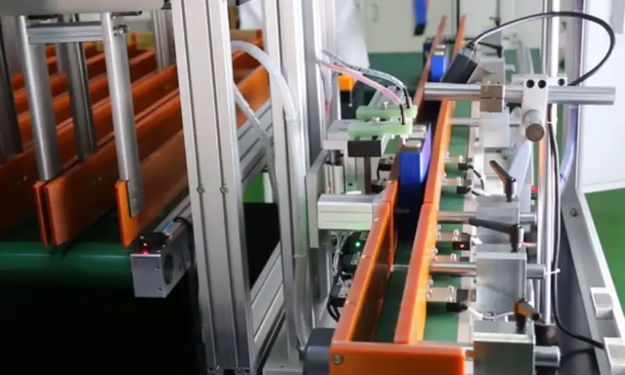
Cells that have passed initial testing are transported to the stacking station. Workers sort the cells and fix them in place using spacers and end plates.

3. Module Incoming
The stacked cell modules are sent to the PACK assembly line for the next process. Modules undergo strict inspection to ensure they meet production requirements.
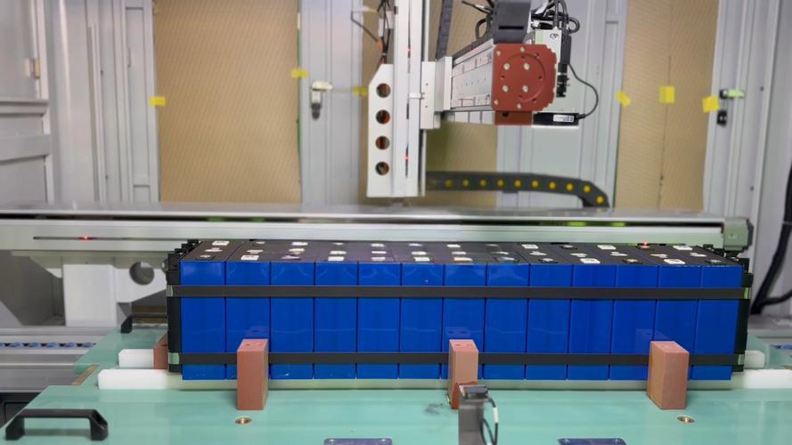
4. Pre-Welding CCD Addressing
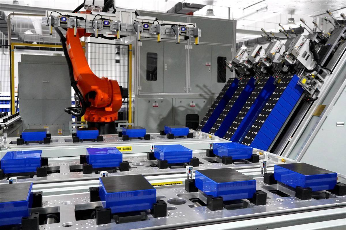
Before welding, a CCD system is used to locate each cell accurately. This ensures correct cell alignment and precise positioning for welding.
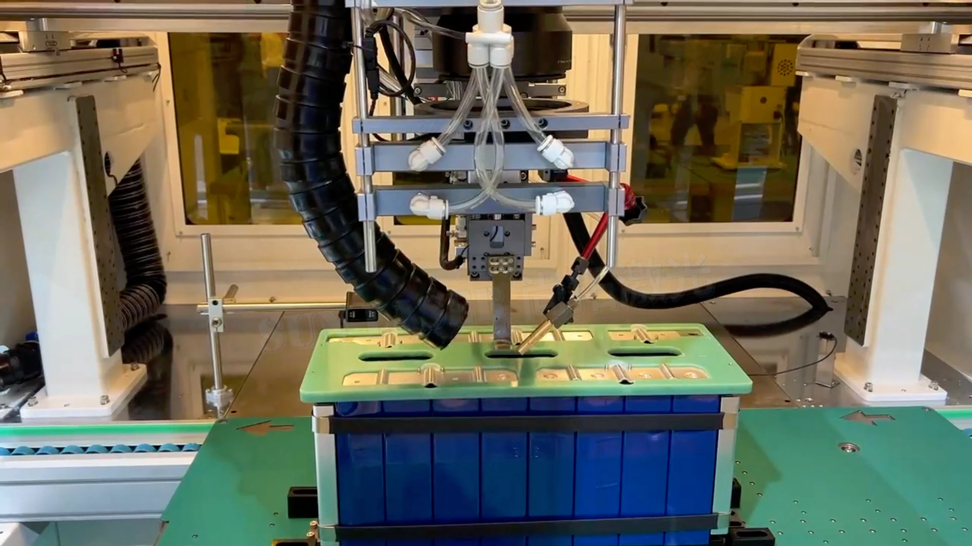
5. Welding and Testing
Cells are welded to ensure reliable and firm connections. After welding, comprehensive tests are conducted, including capacitance, voltage, and current measurements, to ensure module quality and performance.
6. Protection and Installation
Protection boards are installed to prevent overcharging or overdischarging of individual cells. Connectors and cables are attached to the module for integration with other systems.
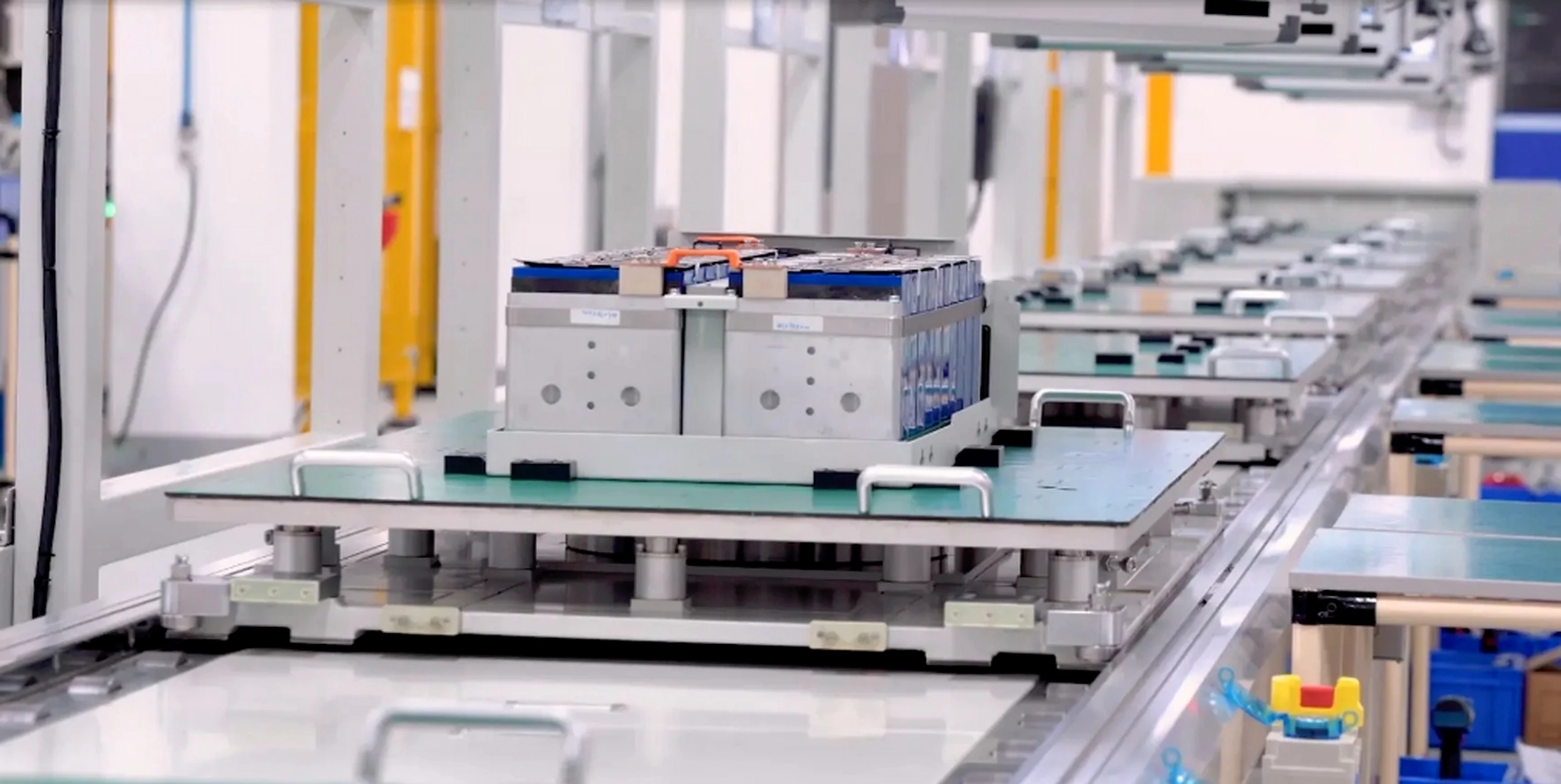
7. Module Testing and Offline
Finally, modules undergo end-of-line (EOL) testing to verify quality and performance. After passing tests, the modules are taken offline, ready for the next process or for packaging and shipment.
Battery PACK Testing Items
1.Function Testing: Ensure all functions of the battery PACK operate normally after assembly into the enclosure. This includes charging and discharging tests, and checking parameters such as voltage, capacity, and energy density to ensure they meet requirements.
2.Safety Testing: Verify the safety performance of the battery PACK, including short-circuit tests, overcurrent protection tests, and temperature tests, to ensure no fire, explosion, or other safety incidents occur during normal use.
3.Environmental Adaptability Testing: Expose the battery PACK to different temperatures, humidity levels, and vibration conditions to test its stability and reliability under various environmental conditions.
4.Reliability Testing: Perform long-term charge and discharge cycle tests to simulate the battery PACK’s lifespan and reliability in real-world usage scenarios.
5.Overall Performance Evaluation: Conduct a comprehensive assessment of the test results to determine whether the battery PACK meets design requirements and make necessary adjustments or improvements.
6.Pre-Market Preparation: If the battery PACK passes all tests and evaluations, it is prepared for market release. This includes product certification, preparing user manuals, and designing packaging.
The Key to Enhancing Battery Pack Performance: Consistency Management
Principle of Reactive Power Compensation in Energy Storage Systems