The three-level architecture of energy storage BMS: BAU, BCU, BMU
2025-09-16

In the Battery Management System (BMSQ), BAU, BCU and BMU represent management units at different levels. They each have different responsibilities and work together to ensure the safe and efficient operation of the entire battery system.

Master Control
The Battery Array Management Unit (BAU)
Also known as BAMS (Battery Array Management System) or MBMS (Multi-Battery Management System), is the highest level in a battery management system (BMS). It is responsible for centrally managing and coordinating the batteries in an entire energy storage plant, ensuring the safe and reliable operation of the battery system under various operating conditions.
Features
- Position: Located at the top level of the entire battery system, it is typically the core control unit of an energy storage plant.
- Key Responsibilities: Comprehensive monitoring, data analysis, decision-making, fault management, communication coordination, data logging and reporting, safety protection, system self-test and diagnosis, and energy management.
- Purpose: Ensures the safe and efficient operation of the entire battery system, optimizes energy use, extends battery life, and provides reliable power output.

Main Responsibilities
Global Monitoring:
- Receives data from all lower-level Battery Cluster Units (BCUs) to comprehensively monitor the status of the entire battery system.
- Key parameters such as voltage, current, and temperature are monitored in real time, and overall battery system performance is evaluated based on this data.
Data Analysis and Processing:
- Comprehensively analyze the collected data to identify potential issues and optimization points.
- Calculate and update battery status parameters such as state of charge (SOC) and state of health (SOH).
- Use complex algorithms to predict the remaining battery life and performance trends.
Decision Making:
- Develop a global charging and discharging strategy based on analysis results to optimize energy efficiency.
- Decide when to perform maintenance and how to adjust battery operating conditions to extend battery life.
Fault Manager
- Centrally manages fault information from each BCU, classifies it, and prioritizes it.
- Provides fault diagnosis reports and recommends appropriate maintenance measures.
- In emergency situations, activates safety protection mechanisms, such as disconnecting the battery pack from the load.
Communication and Coordination:
- Exchanges information with external devices (such as the PCS (Power Conversion System) and EMS (Energy Management System)) via Ethernet or other communication protocols.
- Reports battery array operating status information to upper-level systems.
- Receives instructions from upper-level systems and passes them to the lower-level BCU for execution.
Data Logging and Reporting:
- Records battery system operating data and generates detailed log files.
- Generates regular reports to support subsequent data analysis and maintenance.
Safety Protection:
- Implement multi-layered safety measures to prevent abnormal conditions such as overcharging, over-discharging, and overheating.
- When any condition that could compromise battery safety is detected, immediate action is taken to protect the battery from damage.
System Self-Test and Diagnosis:
- Regularly perform system self-tests to ensure that all components are functioning properly.
- Diagnose potential system issues and provide solutions.
Energy management:
- Incorporates battery SOC/SOH information for system-level energy management and scheduling optimization.
- Works collaboratively with the EMS to optimize energy distribution and improve overall system efficiency.
Main Control
The Battery Cluster Unit (BCU)
The BCU is a mid-level component in the Battery Management System (BMS), responsible for managing and controlling a battery cluster consisting of multiple battery modules.
The BCU is sometimes also referred to as a High Voltaae Unit (HV) or Battery Cluster Management Unit (BCMU).
Key functions at this level include data acquisition, advanced control, fault diagnosis, and communication.
Features
- Position: Located in the middle of the battery system, between the Battery Management Unit (BMU) and the Battery Array Management Unit (BAU).
- Main Responsibilities: Data acquisition and processing, advanced control, fault diagnosis, safety protection, communication interfaces, condition assessment, thermal management, energy management, and contactor control.
- Purpose: Ensures safe and efficient operation of the battery cluster, optimizes energy usage, extends battery life, and provides reliable power output.

Main Responsibilities
Data Acquisition and Processing:
- Receives individual battery data, such as voltage, current, and temperature, from the underlying battery management units (BMUs).
- Performs preliminary processing and integration of this data to generate overall battery cluster status information.
Advanced Control:
- Executes more complex control strategies based on this data, such as adjusting charge and discharge current and voltage.
- Implements balancing management to ensure consistency among battery modules within the battery cluster and prevent overcharging or over-discharging of individual cells.
Fault Diagnosis:
- Utilizes more sophisticated algorithms for fault detection and diagnosis, identifying potential problems.
- When an abnormality is detected, measures are taken to isolate the faulty battery module to prevent the problem from spreading.
Safety Protection:
- Monitors the insulation resistance of the battery cluster to ensure electrical safety.
- In the event of abnormal conditions such as overvoltage, undervoltage, and overtemperature, the circuit is immediately disconnected to protect the battery from damage.
Communication Interface:
- Communicates with the upper-level Battery Array Management Unit (BAU) and other BCUs via standard communication protocols (such as CAN bus or Ethernet).
- Uploads battery cluster status information to the BAU and receives control commands from the BAU.
Status Assessment:
- Calculates and updates battery cluster status parameters, such as state of charge (SOC), and evaluates overall battery cluster performance, providing decision-making support for higher-level systems.
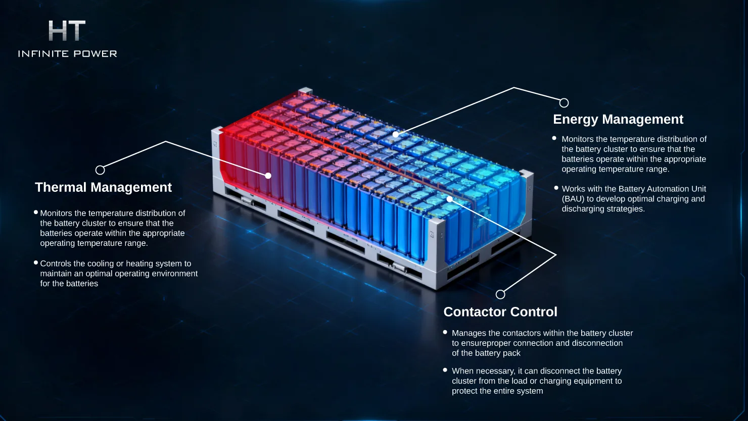
Thermal Management:
- Monitors the temperature distribution of the battery cluster to ensure that the batteries operate within the appropriate operating temperature range.
- Controls the cooling or heating system to maintain an optimal operating environment for the batteries.
Energy Management:
- Optimizes energy distribution and usage based on the battery cluster's status and external demands.
- Works with the Battery Automation Unit (BAU) to develop optimal charging and discharging strategies.

Contactor Control:
- Manages the contactors within the battery cluster to ensureproper connection and disconnection of the battery pack.
- When necessary, it can disconnect the battery cluster from the load or charging equipment to protect the entire system.
Slave Control
The Battery Module Unit (BMU)
Also known as the Cell Supervision Circuit (CSC) or Cell Supervision Unit (CSU), is the lowest level in the Battery Management System (BMS) and directly interfaces with individual battery modules or cells. The BMU's primary responsibility is to monitor and manage individual cells in real time, ensuring their health and preventing any potential damage.
Features
- Location: Located at the lowest level of the battery system, directly connected to individual battery modules or cells
- Main Responsibilities: Data acquisition, balancing management, thermal management, anomaly detection and alarming, communication interface, state estimation, fault diagnosis, insulation monitoring, and hardware protection
- Purpose: Ensures the health of each battery cell, achieves internal balancing within the battery pack, prevents overcharging, over-discharging, overheating, and other issues, and provides accurate data support to the upper-level BCU, thereby ensuring the safety and reliability of the entire battery system.
Main Responsibilities
Data Collection:
- Collects key parameters of individual cells, including voltage, current, and temperature.
- This data is crucial for assessing battery status and forms the basis for decision-making by the upper-level BCU and BAU.
Balancing Management:
- Balancing between individual cells ensures consistency across all cells within the battery pack.
- Using active balancing techniques (such as energy transfer balancing) to balance SOC differences between cells, thereby improving the performance and life of the entire battery pack.
Thermal Management:
- Monitors and controls the temperature around the battery to ensure it remains within a safe operating range.
- Maintaining the battery's optimal operating temperature through heating or cooling systems extends battery life and improves efficiency.
Abnormal Detection and Alarm:
- Detects abnormal conditions in individual cells, such as overvoltage, undervoltage, and overtemperature.
- When an abnormality is detected, an alarm is immediately sent to the BCU so that necessary protective measures can be taken.
Communication Interface:
- Exchanges data with the upper-level BCU via the CAN bus or other communication protocols.
- Uploads collected data to the BCU and receives commands from it.
State Estimation:
- Calculates the state of charge (SOC) and state of health (SOH) of individual cells.
- These key indicators help assess the battery's current condition and remaining lifespan.
Fault Diagnosis:
- Performs preliminary fault diagnosis of individual batteries, identifying potential issues.
- Provides detailed fault information to support higher-level troubleshooting strategies.
Insulation Monitoring:
- Monitors the insulation resistance of batteries and their connecting lines to ensure electrical safety.
- Promptly reports any insulation defects to avoid dangerous situations such as short circuits.
Hardware Protection:
- Controls contactors and other hardware components within the battery module to ensure safe battery operation.
- Disconnects the battery from external circuits when necessary to prevent further damage.
What is the black start technology of energy storage system and its function and principle
Battery Storage Cooling Methods: Air Conditioning vs Liquid Cooling for Large-Scale Systems