Principle of Reactive Power Compensation in Energy Storage Systems
2025-12-05
In power transmission networks, the electrical power delivered from the source to the load consists of two components: active power and reactive power.
1. Active Power, Reactive Power, Apparent Power, and Power Factor
1.1 Active Power (P)
In an AC circuit, the portion of electrical power that is irreversibly converted by resistive components—such as into heat, light, or mechanical energy—is called active power, denoted as P, and measured in watts (W) or kilowatts (kW).
Active power reflects the ability of an AC source to perform work on resistive elements, or the amount of electrical energy converted into other forms of energy per unit time. In essence, it is the average value of the instantaneous power over one AC cycle, and is therefore also referred to as average power. Its magnitude equals half of the maximum instantaneous power, or equivalently, the product of the RMS voltage across the resistor and the RMS current flowing through it.
1.2 Reactive Power (Q)
To describe the phenomenon in which inductive and capacitive components exchange power back and forth with the AC source, this portion of power is defined as reactive power, denoted as Q, and measured in volt-ampere reactive (Var) or kilovolt-ampere reactive (kVar).
In AC circuits, components with inductance or capacitance build magnetic fields (in inductors) or electric fields (in capacitors) after being energized. During the first half of each AC cycle (when instantaneous power is positive), these components absorb energy from the source to establish their fields. During the second half of the cycle (when instantaneous power is negative), the stored field energy is returned to the source. As a result, the average value of this power over a full cycle is zero—meaning no net energy is consumed. It represents a reversible energy exchange between the source and the magnetic or electric fields.
Reactive power quantifies the maximum rate at which this exchange occurs. In practical systems, inductive loads—such as motors and transformers—consume reactive power to build their operating magnetic fields. Without sufficient reactive power, these devices cannot maintain their electromagnetic conditions, resulting in reduced voltage and unstable operation.
Negative Impacts of Reactive Power on Power Generation and Consumption
Excessive reactive power demand creates several adverse effects:
(1).Reduces the active power output capability of generators.
(2).Lowers the power delivery capacity of transmission and distribution equipment.
(2).Lowers the power delivery capacity of transmission and distribution equipment.
(3).Increases voltage drops and power losses along transmission lines.
(4).Leads to low power factor operation and voltage depression, preventing electrical equipment from operating at rated capacity.
The reactive power supplied by generators and high-voltage transmission lines is far from sufficient to meet load demand. Therefore, power systems must be equipped with reactive power compensation devices to provide additional reactive power and maintain rated voltage levels for end-users. This is the fundamental reason why reactive power compensation is necessary in electrical networks.
1.3 Apparent Power (S)
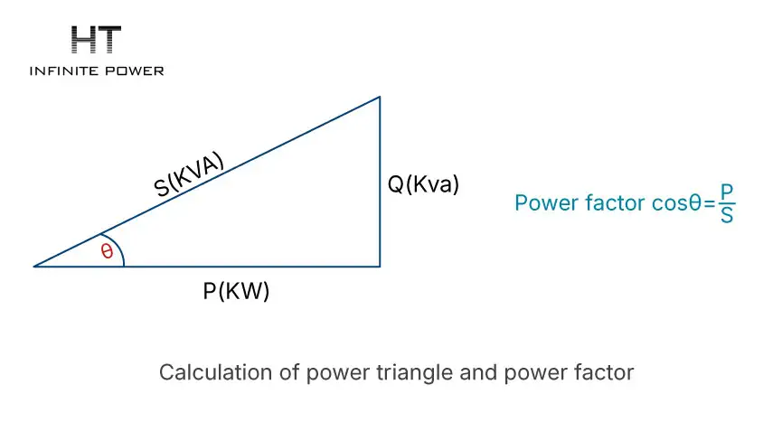
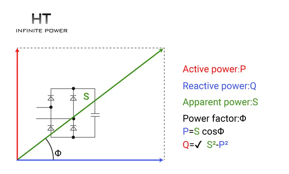
The total power that an AC source can supply is called apparent power, represented by S. Numerically, it equals the product of the voltage and current in an AC circuit. Apparent power is measured in volt-amperes (VA) or kilovolt-amperes (kVA), and is commonly used to rate the capacity of AC equipment such as transformers.
Apparent power is neither equivalent to active power nor to reactive power; rather, it encompasses both. Whether a transformer with an apparent power rating of 100 kVA can deliver 100 kW of active power depends primarily on the power factor of the load.
1.4 Power Factor (PF)
The phase angle between sinusoidal AC voltage and current is called the power factor angle, denoted by Φ (phi). It has no unit. The cosine of this angle is referred to as the power factor (PF). Power factor is determined by the characteristics of the circuit components and the operating frequency.
In a purely resistive circuit, the power factor equals 1; in a purely inductive or capacitive circuit, the power factor equals 0.
The mathematical expression is:
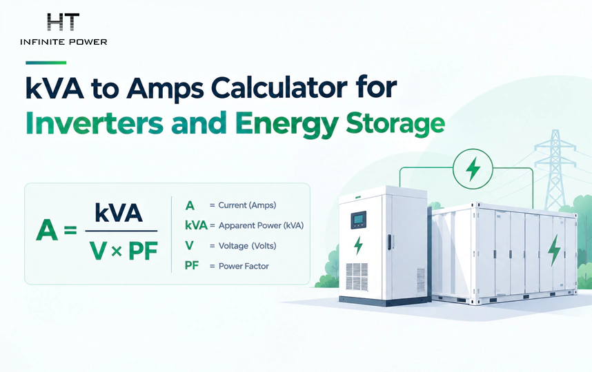
Power Factor = Active Power / Apparent Power or cos Φ = P / S
2. Reactive Power Compensation Devices
What types of devices are used for reactive power compensation? You may already be familiar with shunt capacitor banks, synchronous condensers, SVC (Static Var Compensator), and SVG (Static Var Generator), also known as STATCOM.
Today, we will walk through the development, working principles, and characteristics of each type of reactive compensation device.
A general drawback of early reactive power compensation devices is their slow response speed, which makes them unsuitable for rapidly changing reactive power demands.
2.1 Synchronous Condenser
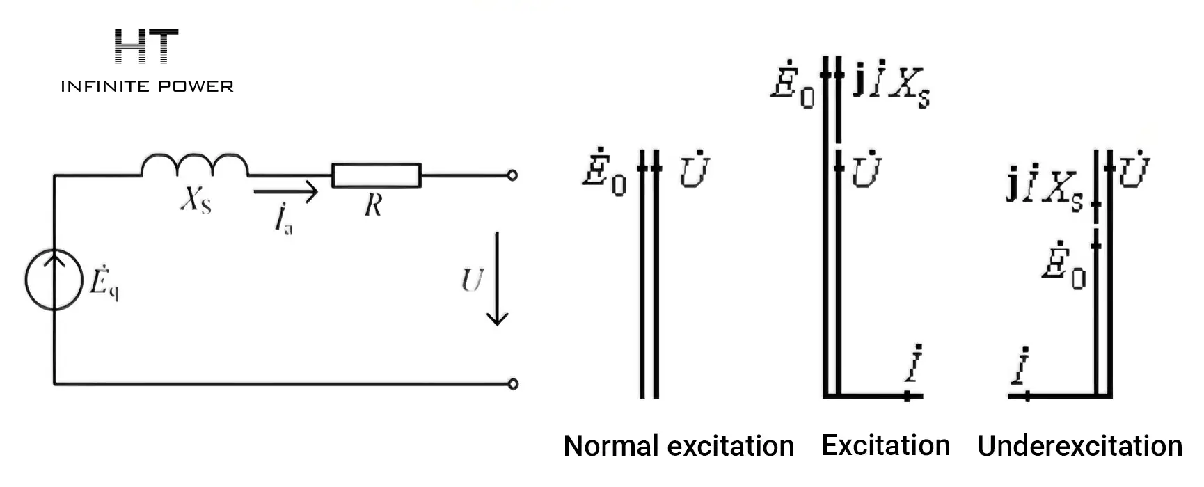
A synchronous condenser is essentially a large synchronous motor operating under no-load conditions. It can operate in two excitation modes: over-excitation and under-excitation.
In over-excited operation, the synchronous condenser delivers inductive reactive power to the system (or equivalently, absorbs capacitive reactive power).
In under-excited operation, it absorbs inductive reactive power from the system (or equivalently, provides capacitive reactive power).
2.2 Shunt Capacitors
Shunt capacitors are inexpensive and easy to operate and maintain. They can be installed in a distributed manner at the user side to achieve local reactive power compensation and maintain reactive power balance. Because of these advantages, they are widely used in power systems.
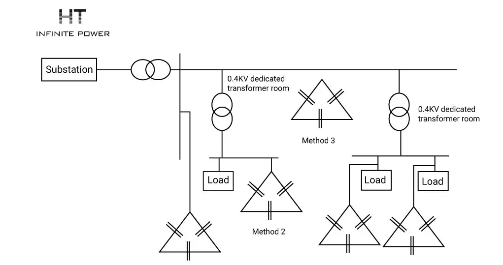
Drawbacks:Shunt capacitors have poor reactive power regulation capability, or equivalently, poor voltage regulation performance. The amount of reactive power they supply is proportional to the square of the bus voltage. In addition, they can only supply capacitive reactive power (or equivalently, absorb inductive reactive power) and cannot provide inductive reactive power when needed.

Parallel capacitor banks are sensitive to harmonics, and the presence of harmonics in the power grid can lead to capacitor bank failures.
2.3 SVC (Static Var Compensator)
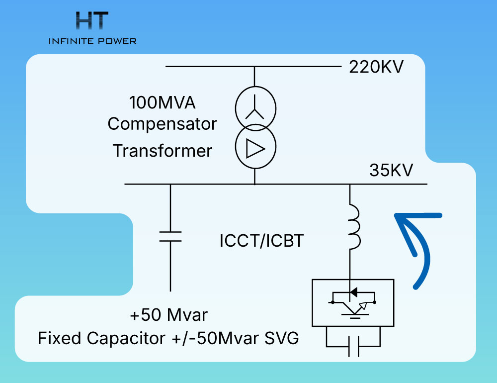
A Static Var Compensator (SVC) is primarily composed of reactors, capacitors, and thyristors. The SVC provides bidirectional reactive power regulation, meaning it can compensate for both inductive and capacitive reactive power. Its operation and maintenance are relatively simple, and it responds very quickly.
2.4 SVG (Static Var Generator)
The SVG (Static Var Generator) uses capacitors as energy storage elements and diodes in a self-commutated bridge configuration. It is connected in parallel to the power grid, converting the DC-side voltage into AC voltage at the same frequency as the grid. This allows the SVG to both absorb and supply reactive power. It features fast response and produces minimal harmonic currents.
3.Reactive Power Compensation Principle of Energy Storage Systems
Energy storage converters can operate in all four quadrants, allowing them to simultaneously supply or absorb both active and reactive power, and they also provide frequency and voltage regulation. Reactive power compensation in energy storage systems is achieved through charging and discharging operations, enabling the system to supply or absorb reactive power for the grid. This helps improve the power factor and voltage stability of the power system while reducing the impact of reactive power on the grid.
Specifically, when the power system experiences a shortage of reactive power, the energy storage system can output reactive power to enhance voltage stability. Conversely, when there is an excess of reactive power, the system can absorb it to prevent overvoltage. In situations with high reactive power demand, the energy storage system can discharge to provide reactive power, improving overall operational efficiency and reducing line losses.
When the voltage deviates from its rated value, the system can precisely regulate the output or absorption of reactive power, maintaining stable grid voltage and preventing damage caused by overvoltage or undervoltage. Compared with traditional reactive power compensation devices—such as Static Var Compensators (SVCs) or Static Var Generators (SVGs)—energy storage systems offer greater flexibility, efficiency, and reliability.
Energy Storage Battery PACK: Understanding the Core of Energy Storage Technology
Comparative Analysis of Primary and Secondary Frequency Regulation in Energy Storage Power Stations