Energy Storage System Integration: Two Architectures, Two Equipment Configurations
author: HT Infinite Power
2026-10-16
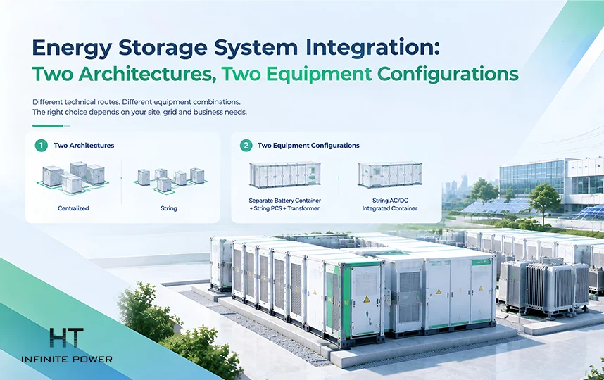
Energy storage system integration has developed along two main technical routes: centralized and string architecture. Within the string route, two different equipment configurations have also emerged.
The first distinction is architectural: whether battery clusters are paralleled or electrically decoupled on the DC side.
The first distinction is architectural: whether battery clusters are paralleled or electrically decoupled on the DC side.
The second is equipment configuration: within a string architecture, whether the system uses a separate battery container with a string PCS and transformer unit, or a string AC/DC integrated container.
These choices affect more than equipment arrangement. They influence efficiency, usable discharged energy, availability, fault boundaries, DC cabling, safety, construction, commissioning, and lifecycle economics.
For EPC contractors, system integrators, and project developers, neither architecture should be treated as universally superior. The appropriate configuration depends on site conditions, grid requirements, operating profile, construction schedule, and the project's cost model.
1. Centralized vs. String BESS: The Fundamental Architecture Difference
DC-Side Parallel Connection vs. Electrical Decoupling
A traditional centralized BESS typically consists of a battery container and a centralized PCS/transformer unit. Multiple battery clusters are connected in parallel on the DC side and feed a high-capacity centralized PCS. The PCS performs the DC/AC conversion before the power is stepped up for grid connection.
Large single-unit capacity, fewer power-conversion devices, a relatively simple aggregation structure, and a mature supply chain have made centralized architecture a long-established approach.
A string BESS takes a different approach. The system is divided into independently operated units, with each battery cluster connected to its own string PCS. In a typical one-cluster-one-PCS configuration, the battery clusters are managed independently and are not directly paralleled on the DC side. Their AC outputs are then aggregated before being stepped up for grid connection.
The fundamental difference is therefore the DC-side topology: parallel connection or electrical decoupling.
With DC-side parallel connection, multiple battery clusters share a common electrical path. Differences in cell and cluster internal resistance, temperature, and SOC can affect current distribution and operating consistency. Under suitable conditions, voltage differences between parallel branches can also contribute to circulating current.
String architecture electrically decouples the battery clusters. Each cluster has its own PCS and power-conversion path, reducing direct electrical coupling between clusters and providing finer control granularity.
Architecture and Configuration Comparison
| Parameter | Centralized BESS | String BESS |
| DC-side topology | Battery clusters connected in parallel | Battery clusters electrically decoupled |
| PCS configuration | Centralized PCS | One PCS per battery cluster |
| Cluster management | Centralized | Cluster-level |
| DC-side coupling | Higher | Lower |
| Power conversion | Centralized | Distributed |
| Main advantages | High unit capacity, mature supply chain, centralized management | Independent cluster control, finer fault granularity |
| Main considerations | Common DC-side path and larger centralized fault boundary | Higher PCS count and greater equipment integration |
3. Availability and Fault Isolation
What Happens When One PCS Fails?
One of the clearest architectural differences is the amount of capacity affected by a single PCS failure.
In a string architecture, each battery cluster has its own PCS. If one PCS becomes unavailable, the corresponding cluster can potentially be isolated while the remaining units continue operating, subject to the system's protection and control design.
This creates a smaller fault boundary. During maintenance, the affected cluster can remain offline while other units continue participating in grid dispatch or market operation.
In a centralized configuration, multiple battery clusters are connected through a high-capacity central PCS. If that PCS becomes unavailable, the battery capacity connected through it may have to exit operation together.
The actual availability impact therefore depends on the system topology, protection scheme, operating strategy, and contractual availability requirements.
For projects with strict availability requirements, fault granularity should be evaluated alongside initial equipment cost. The relevant engineering question is not only the rated MW of the PCS, but also how much battery capacity is exposed to a single PCS failure.
4. Separate String Systems vs. String AC/DC Integrated Containers
String architecture does not by itself determine the physical arrangement of the equipment. Two different equipment configurations can use the same basic one-cluster-one-PCS architecture.
Separate String Configuration
In a separate string configuration, the battery clusters remain in an independent battery container, while the string PCS units are installed in a separate PCS and transformer container.
The AC-side power-conversion granularity is therefore finer than in a centralized system, but the battery and PCS equipment remain physically separated.
Because of this arrangement, DC cables must run from the battery container to the PCS equipment. This creates additional cable routes, connection points, mechanical protection requirements, insulation testing, and field commissioning work.
Cable lengths can also vary between battery clusters. Differences in cable impedance should be considered during system design because they can affect the electrical characteristics of individual DC branches.
String AC/DC Integrated Container
A string AC/DC integrated container takes the integration one step further by placing the battery clusters and corresponding string PCS units inside the same standard 20-foot container.
The one-cluster-one-PCS architecture remains unchanged. The main difference is that the DC connection is made locally inside the container rather than through long external cable runs.
The AC outputs are then aggregated inside the container before being connected to the transformer and grid.
This configuration therefore combines two concepts:
electrical decoupling between battery clusters and physical integration of the battery and PCS equipment.
That distinction is important when comparing string BESS solutions. A reference to "string architecture" alone does not fully describe the physical DC arrangement.
Separate String vs. AC/DC Integrated Configuration
| Parameter | Separate String BESS | String AC/DC Integrated Container |
| Battery and PCS arrangement | Separate containers | Same container |
| PCS architecture | One PCS per battery cluster | One PCS per battery cluster |
| DC connection | Between battery and PCS containers | Inside the container |
| External DC cabling | Required | Significantly reduced |
| Cluster-level control | Available | Available |
| Factory integration | Lower | Higher |
| Field installation | More DC connection work | More work completed before delivery |
| Main consideration | Flexible equipment arrangement | Compact integration and reduced external DC work |
5. Why Keeping the DC Circuit Inside the Container Matters
Reduced External DC Cabling
Keeping the DC circuit inside the container is one of the most visible differences between a string AC/DC integrated container and a separate string configuration.
In a separate string system, the battery container and PCS equipment are physically separated, requiring high-voltage DC cables to cross between them.
For example, in a system with 12 battery clusters, the arrangement described in the original design involves 24 high-voltage DC cables. More cables also mean more connection and fixing points that must be installed, inspected, and commissioned.
Cable length can vary between battery clusters, producing differences in branch impedance.
In an integrated container, the battery clusters and string PCS units are installed together. The DC connection is made locally, reducing the external DC cable path from a cross-container distance of tens of meters to a much shorter internal connection.
This provides three practical benefits: reduced external high-voltage DC exposure, shorter DC paths, and greater factory integration of the connection and testing process.
Electrical Safety
High-voltage DC circuits require careful protection because faults can involve sustained arcing and significant fault energy.
Keeping the DC circuit inside the container reduces externally exposed high-voltage DC wiring and the number of field-installed high-voltage connection points. This can reduce the exposure associated with external DC cable routes and field terminations.
However, electrical decoupling does not eliminate battery-level thermal-runaway risk.
Battery systems still require appropriate module-, pack-, and container-level protection according to the battery design, system topology, applicable standards, and project fire-safety requirements.
Installation and Commissioning
Integrating the battery and PCS equipment can shift more work from the project site to the factory.
DC connections can be prefabricated and tested before shipment, reducing the amount of field cable termination, insulation testing, communication testing, and charging/discharging verification required after installation.
For large projects, reducing field-installed DC connections can simplify coordination between battery equipment, PCS equipment, protection systems, and the site control network.
The benefit is therefore not simply fewer cables. It is also the reduction of field interfaces that must be installed, inspected, tested, and commissioned.
6. Footprint and Construction Efficiency
Compact Equipment Arrangement
A string AC/DC integrated container eliminates the need for a separate external PCS container and reduces external DC cabling. Under comparable system conditions, this can produce a more compact equipment arrangement.
The original design indicates that the integrated configuration can reduce occupied area by approximately 30%. The actual result depends on equipment dimensions, required clearances, fire-safety provisions, access routes, and site layout.
The value of reduced footprint depends strongly on project location. At land-constrained load centers, a smaller BESS footprint can have direct economic value. At large renewable-energy sites where land is readily available, the benefit may carry less weight.
Factory Integration and Construction
A factory-integrated unit can arrive with battery and PCS equipment already installed and partially tested.
This can reduce several site activities, including PCS installation, DC wiring, communication testing, and charging/discharging verification.
For large projects, the resulting reduction in field integration can help shorten installation and commissioning work. The actual schedule remains dependent on project scale, logistics, grid-connection requirements, and site conditions.
The value of faster commissioning is not limited to construction cost. Earlier grid connection can allow the BESS to begin generating project revenue sooner.
7. Safety, Grid-Forming, and Intelligent Operation
Safety and Fault Boundaries
Safety should be evaluated at both the electrical-architecture and equipment levels.
In a centralized DC architecture, a common DC path can collect current from multiple battery clusters. Depending on the topology and protection design, a DC fault can therefore involve a larger amount of available fault energy.
In a string architecture, each DC branch corresponds to an individual battery cluster and PCS. This can provide a smaller electrical fault boundary and more granular isolation.
The distinction should not be simplified into one architecture being inherently safe and the other unsafe. Cell-level thermal events remain possible in either configuration.
Battery-level protection, thermal management, monitoring, and appropriate fire-protection systems therefore remain necessary regardless of the selected architecture.
Grid-Forming Capability
Grid-forming capability is fundamentally a PCS control function rather than an exclusive feature of centralized or string architecture.
A centralized PCS can support grid-forming functions when the PCS control system and project configuration provide the required capability. String PCS systems can also implement grid-forming functions when the individual PCS units and system controller are designed accordingly.
For weak-grid projects, engineers should therefore evaluate actual PCS control performance, synchronization, voltage and frequency support, protection coordination, and grid-interconnection requirements rather than assuming that architecture alone determines grid-forming capability.
Intelligent Operation and Maintenance
String architecture provides more granular operating information because each battery cluster and PCS has an independent operating path.
A coordinated EMS can collect and manage information including battery voltage, temperature, SOC, PCS operating status, power output, alarms, and historical operating data.
For an integrated system, battery data, power commands, protection functions, and dispatch strategies can be coordinated within a common control architecture. This can simplify communication between battery, PCS, and control systems and support more direct fault analysis.
High-speed communication architectures can also coordinate large numbers of string PCS units for functions such as AGC/AVC dispatch, inertia-related control, weak-grid operation, and grid-forming or black-start applications, depending on the system design.
Time-series operating data can further support operating-condition analysis and fault investigation by allowing engineers to trace battery and PCS behavior over specific periods.
8. Cost, Lifecycle Economics, and Architecture Selection
Initial CAPEX vs. Lifecycle Cost
Technical performance alone does not determine the appropriate BESS architecture.
Centralized systems can have structural cost advantages because of their large single-unit capacity, lower number of power-conversion devices, simpler DC aggregation, mature supply chains, and common spare parts.
For projects that are highly sensitive to initial CAPEX, have relatively simple electricity-price structures, have less stringent availability requirements, or have sufficient land, centralized architecture can remain economically attractive.
A string AC/DC integrated container can require more distributed PCS equipment and a higher initial investment. Its potential value is realized through operating performance and project execution over the system lifecycle.
The economic factors can include:
- Usable discharged energy: The original design identifies a 10% DOD advantage for the string AC/DC integrated configuration under the stated comparison conditions. The economic value depends on the electricity-price spread and annual cycling profile.
- Downtime exposure: If a fault affects one battery cluster instead of a larger centralized capacity block, the corresponding loss of operating capacity can be reduced.
- Commissioning time: Factory integration can reduce site installation and commissioning work, creating potential time-to-revenue value.
These benefits should be quantified against the additional CAPEX rather than assumed.
A lifecycle assessment should consider initial investment, annual cycles, electricity-price structure, usable energy, degradation, auxiliary consumption, availability, maintenance requirements, replacement costs, and project lifetime.
Selecting the Appropriate Technical Route
A string AC/DC integrated container may be suitable for projects with:
- Limited land availability and a need for compact deployment
- Tight grid-connection or commissioning schedules
- Large peak-to-valley electricity-price spreads and frequent cycling
- Strict availability requirements or contractual availability penalties
A centralized or separate string configuration may remain appropriate for projects with:
- Ample land, such as large renewable-energy sites
- Strong sensitivity to initial CAPEX
- Existing centralized infrastructure requiring expansion
- A preference for standardized spare parts and centralized maintenance
For weak-grid projects requiring grid-forming support, both centralized and string architectures can be technically viable. The decisive factor should be the PCS control performance demonstrated under the project's actual grid conditions.
The architecture should ultimately be selected according to the complete project model rather than a single performance indicator.
Conclusion
Centralized and string BESS architectures represent different approaches to connecting battery clusters with power-conversion equipment.
The centralized approach uses DC-side parallel connection, high-capacity centralized PCS equipment, and mature supply-chain advantages to control initial system cost. String architecture gives each battery cluster an independent PCS and electrical path, providing finer cluster-level control and a smaller fault boundary.
Within string architecture, the physical equipment configuration creates another important distinction. A separate string system keeps the battery and PCS equipment in different containers, while a string AC/DC integrated container places them together and keeps the DC connection inside the equipment.
That integration can reduce external high-voltage DC cabling, field connection work, and equipment footprint while shifting more installation and testing into the factory.
The trade-off is that a more integrated string solution can require higher initial investment. Its potential value comes from usable discharged energy, availability, reduced field work, and commissioning time.
For BESS system integration, the appropriate architecture should not be selected simply by asking which technology is more advanced. The decision should be based on the project's electrical topology, operating profile, grid requirements, site constraints, construction strategy, and lifecycle economics.
Top Battery Manufacturers in 2026: Global Leaders and BESS Suppliers
Related Article